
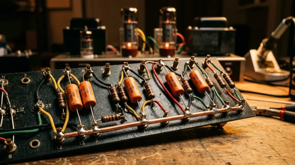
More importantly, building a high-voltage tube amplifier requires a layout that handles extreme heat and physical vibration. A custom turret board provides the perfect mechanical and electrical foundation for these demanding circuits.
Choosing your substrate is your first critical decision. Vintage builds often use traditional phenolic board. However, modern high-performance designs rely on rugged Garolite G10 or GP03 fiberglass. These materials prevent electrical arcing and easily withstand high operating temperatures.
In practice, to get started, you must map your layout in CAD software to prevent ground loops. Once your schematic is finalized, you will need the right fabrication gear. This process includes choosing between heavy-duty turrets and classic eyelets, along with a reliable benchtop staking tool. Fortunately, specialized suppliers make it easy to purchase raw sheets, tools, or pre-made vintage-style circuit boards. This guide will walk you through every step of the design.
Understanding the Turret Board in Tube Amplifier Design
To transform these raw materials into a functional, noise-free circuit, you must master the systematic layout process. Designing a turret board for a high-voltage tube amplifier requires balancing mechanical stability with electrical isolation. Consequently, you must plan your physical layout with extreme precision before drilling your board material.
Step 1: Draft the Physical Footprint
First, measure your internal chassis dimensions to determine your maximum board size. You must maintain at least a 0.5-inch clearance between the edge of the board and the chassis walls to prevent high-voltage arcing.
Step 2: Group Components by Signal Stage
Next, arrange your components chronologically following the schematic signal path. Keeping the input stage physically separated from the power supply section minimizes the risk of parasitic oscillation. In addition, orient your components to keep high-voltage plate lines away from sensitive grid-leak resistors.
Step 3: Define Spacing and Drill Specifications
Before drilling your substrate, you must establish exact spacing for your mounting hardware. Components must sit flat against the board without stretching their leads. The following table outlines the standard physical design parameters for a reliable layout:
| Parameter | Standard Specification | Purpose |
|---|---|---|
| Turret-to-Turret Spacing | 1.0″ to 1.5″ (25.4 to 38.1 mm) | Accommodates standard axial coupling capacitors |
| Board-to-Chassis Clearance | Minimum 0.5″ (12.7 mm) | Prevents high-voltage arcing to the metal chassis |
| Drill Hole Diameter | 0.109″ (2.77 mm) | Matches the shank of standard swage turrets |
| Minimum Edge Distance | 0.25″ (6.35 mm) | Prevents fracturing the substrate during staking |
Step 4: Establish the Grounding Path
Once your component placement is set, plan the route for your ground bus wire. Run a heavy-gauge solid copper wire across the ground turrets to act as your local ground path. This structured path ensures low resistance and eliminates the stray ground loops that cause audible hum.
Step 5: Finalize the Drill Template
Print your finalized CAD layout at a 1:1 scale on paper. Tape this paper template directly onto your Garolite G10 or phenolic board substrate. This template acts as your precise visual guide for center-punching each hole before using your drill press and staking tool.
What is a Turret Board and How Does It Work?
Once you have taped your paper template securely to the Garolite G10 or phenolic board substrate sourced from suppliers like McMaster-Carr, you are ready to execute the physical fabrication phase of your tube amplifier layout. Consequently, your precision at this stage directly dictates the mechanical integrity of your circuit.
First, use an automatic center punch to mark the exact center of each drill point through the paper, Because the punch creates a physical dimple, your drill bit will not wander when you begin machining. Next, remove the paper template and prepare your drill press. You must use sharp high-speed steel or carbide-tipped drill bits because glass-epoxy laminates like GP03 fiberglass quickly dull standard steel bits. When drilling these materials, always wear a particulate mask to protect your lungs from fine glass dust.
After drilling all the holes to match your terminal shank diameter, clear away any burrs from the edges. Now, prepare your staking tool and anvil to set your selected hardware. If you are using classic brass eyelets, use a roll-setting die to flare the metal smoothly. For heavy-duty turrets, set your benchtop staking tool to apply firm, even vertical pressure. This pressure swages the shank outward against the underside of the board, locking the terminal tightly in place without fracturing the surrounding substrate. Once all terminals are staked securely, inspect each joint visually to ensure zero mechanical play before you begin mounting your components.
Turret Boards vs. PCBs and True Point-to-Point Wiring
Once your physical terminals are staked and secure, you must systematize your layout approach to translate your tube amplifier schematic into a clean, physical reality. Designing a custom layout requires structured planning to ensure both high-voltage safety and mechanical stability.
Step 1: Group Components Logically
First, map out your components on graph paper or CAD software exactly as they flow in your circuit diagram. Group your high-voltage plate resistors far away from sensitive input grid lines so that you prevent parasitic coupling and unwanted hum in the audio path.
Step 2: Select Your Board Material
Next, select a high-quality 3/32-inch Garolite G10 sheet rather than a cheap, moisture-prone paper phenolic board. You should source this raw stock from industrial suppliers like McMaster-Carr to guarantee your material is perfectly flat and free of internal voids.
Step 3: Establish Component Spacing
Once your material is selected, space your turret terminals to match the physical length of your components. You must maintain at least 1.5 to 2 inches of spacing for large axial capacitors so that their body weight lies flat against the board, which prevents the leads from fracturing under physical vibration.
Step 4: Map the Ground Bus
After organizing your signal components, plan a thick 14 AWG solid copper ground bus along the bottom edge of the board. Connect your local circuit grounds to this bus using brass eyelets or dedicated ground turrets to establish a low-resistance path to your chassis, which eliminates ground loops.
Step 5: Finalize Layout and Drill Template
Finally, print your layout scale template on paper and tape it directly to your Garolite G10. Before drilling, use your center punch on every marked terminal node to guide your drill bit, which ensures your staking tool aligns perfectly during final assembly.
Selecting the Right Turret Board Materials
With your physical template punched and aligned, you must execute the design steps systematically to ensure your raw materials handle the mechanical stresses of assembly. Designing a rugged, high-voltage layout requires balancing the physical dimensions of your components with the electrical and mechanical limits of your chosen substrate.
Step 1: Specify Your Substrate and Sourcing
First, select a high-grade 1/8-inch (3.17 mm) sheet of Garolite G10 or GP03 fiberglass from industrial suppliers like McMaster-Carr. You must avoid thin or cheap phenolic board because high-voltage tube amplifier circuits will carbonize and track current across these low-grade substrates if moisture enters the workshop.
Step 2: Calculate Structural Clearances
Next, map your hole locations so that no turret center sits closer than 0.25 inches from any board edge. Maintaining this distance is critical because the immense radial pressure applied by your staking tool will split the laminated glass layers if holes are placed too close to the border.
                  [ 0.25" Min. Edge Clearance ]
  +---------------------------------------------------------+
  |                                                         |
  |      ( O )  <-- Turret Hole                             |
  |        |                                                |
  |        v                                                |
Step 3: Match Material Properties to Staking Specifications
Refer to the engineering metrics below to select the appropriate material thickness and tooling setup. Consequently, your physical design footprint must accommodate these structural realities before you begin drilling.
| Substrate Material | Dielectric Strength | Recommended Thickness | Tooling Requirement | Risk of Material Fracture |
|---|---|---|---|---|
| Garolite G10 (FR4) | 500 V/mil | 1/8″ (3.17 mm) | Carbide drill bits | Low (Highly durable) |
| GP03 Fiberglass | 400 V/mil | 1/8″ (3.17 mm) | Carbide/HSS bits | Moderate (Brittle edges) |
| Paper Phenolic | 250 V/mil | 3/32″ (2.38 mm) | Standard HSS bits | High (Delaminates easily) |
Step 4: Verify Shank Exposure for Eyelets and Turrets
Before purchasing your hardware, measure the shank length of your turrets or eyelets against your board thickness. You must ensure that 0.062 to 0.093 inches of the terminal shank protrudes through the bottom of the board so that your staking tool has sufficient metal to roll a secure, tight flange without fracturing the surrounding glass-epoxy matrix.
Garolite G10/FR4 vs. GP03 Fiberglass
Once you have verified the correct shank exposure for your eyelets or turrets, you must execute the layout steps to prevent material failure during the machining of your selected substrate. This step-by-step process ensures your tube amplifier layout remains mechanically stable under the impact of a staking tool.
Step 1: Establish Edge Clearance Based on Material Toughness
First, map out your drilling boundaries by enforcing the 0.25-inch minimum edge clearance constraint, Because Garolite G10 has exceptional shear strength, it can withstand the radial force of staking near this limit. In contrast, GP03 fiberglass has brittle edges that will fracture if you place holes too close to the border. Consequently, you should increase the edge clearance to 0.30 inches when utilizing GP03 to prevent the laminate from splitting or blowing out during fabrication.
Step 2: Pitch Holes to Prevent Arc-Over
Next, calculate the physical distance between your components based on the dielectric strength of your board, While a phenolic board only offers 250 V/mil of isolation, Garolite G10 easily handles high-voltage nodes. For this reason, you can safely space high-voltage joints closer on G10, though you must maintain a minimum of 0.375 inches between adjacent turret holes to prevent carbon tracking in high-humidity environments.
Step 3: Select Tooling and Source Raw Stock
Finally, prepare your fabrication tools and raw materials. If you source raw sheets from industrial suppliers like McMaster-Carr, specify the exact thickness needed to match your turret shank length. When drilling Garolite G10, avoid standard high-speed steel bits because the dense glass fibers will dull the cutting edges instantly. Instead, use carbide drill bits to achieve clean, burr-free holes that allow your staking tool to seat the hardware flush against the board surface.
Why Wood and Plexiglass Are Unsuitable for Amp Builds
Once you have your tooling selected, you must apply these fabrication steps exclusively to industrial laminates, completely ruling out sub-standard materials like wood or plexiglass during the design phase. Using inappropriate materials in a high-voltage tube amplifier leads to catastrophic physical failures.
Step 1: Analyze Thermal and Dielectric Limits
Before cutting any board stock, calculate the thermal and electrical loads of your specific circuit. High-voltage tube amplifiers frequently operate at internal chassis temperatures exceeding 85°C, with node voltages surpassing 450 VDC. Under these conditions, domestic woods absorb ambient moisture. This moisture absorption drops their dielectric isolation to near-zero and causes high-voltage arc-over.
Similarly, plexiglass (acrylic) begins to soften and deform at temperatures as low as 80°C. This thermal instability causes the board to warp under the weight of heavy transformers and power resistors. As a direct result, you risk short circuits against the metal chassis.
Step 2: Compare Mechanical and Electrical Material Specs
To visualize these physical limitations, compare the critical mechanical and electrical thresholds of these materials before finalizing your layout.
| Material | Dielectric Strength (V/mil) | Max Operating Temp (°F / °C) | Moisture Absorption (%) | Risk of Structural Failure |
|---|---|---|---|---|
| Garolite G10 | 500 | 284°F / 140°C | < 0.10% | Extremely Low (Highly stable) |
| Phenolic Board | 250 | 250°F / 121°C | < 1.50% | Moderate (Prone to chipping) |
| Plexiglass (Acrylic) | 400 | 160°F / 71°C | < 0.30% | High (Melts and cracks under stress) |
| Softwood / Hardwood | < 50 (Variable) | 200°F / 93°C (Combustible) | 10% – 20% | Critical (Carbon tracking and fire) |
Step 3: Assess Physical Stresses Under Staking Pressure
Finally, calculate the mechanical impact forces applied during component assembly. Setting eyelets or turrets requires a heavy downward strike from a manual or pneumatic staking tool. This radial force splits brittle plexiglass instantly, radiating micro-fractures from the hole edge.
If you attempt to stake hardware into wood, the soft fibers compress permanently instead of resisting the tool pressure. Consequently, the turret neck will not form a tight, permanent roll flange. Over time, the physical vibration of the amplifier speakers will loosen the hardware. This loose fit causes intermittent solder joints and eventual electrical failure. Therefore, you must specify Garolite G10 or high-grade GP03 fiberglass from suppliers like McMaster-Carr to guarantee structural survival.
Matching Board Thickness to Turret Height and Staking Specs
Selecting a structurally sound substrate like Garolite G10 is only the first step. To ensure the long-term electrical integrity of your tube amplifier, you must precisely match the board thickness to your turret shank length and staking tools. If the turret shank is too short, the staking tool cannot form a complete roll flange on the underside. Consequently, the turret will wobble, causing intermittent contact or cracked solder joints under thermal stress. Conversely, if the shank is too long, the tool will crush or bend the brass instead of rolling it cleanly. This error leads to micro-fractures, sharp metal edges that invite high-voltage arcing, or a loose assembly.
To prevent these failures, you must calculate your mechanical tolerances before purchasing your raw materials or hardware.
Step 1: Establish Your Board and Shank Metrics
As a strict engineering rule, the turret shank must protrude exactly 1/32” to 3/64” (0.8 mm to 1.2 mm) beyond the board’s bottom face before you begin staking. This specific protrusion provides just enough metal to form a tight, permanent mechanical roll flange against the board without splitting the brass.
The table below outlines the standard design specifications for common board materials, including Garolite G10, GP03 fiberglass, and vintage-style phenolic board options sourced from industrial suppliers like McMaster-Carr.
| Board Thickness | Recommended Turret Shank Length | Drill Bit Size (Clearance Fit) | Target Staking Tool Profile | Recommended Application |
|---|---|---|---|---|
| 1/16″ (1.59 mm) | 0.093″ to 0.109″ (2.38 to 2.77 mm) | #42 or 3/32″ (2.38 mm) | Miniature Radial Roll | Light-duty preamp boards; space-constrained chassis |
| 3/32″ (2.38 mm) | 0.125″ to 0.140″ (3.18 to 3.56 mm) | #31 or 1/8″ (3.18 mm) | Standard Radial Roll | Industry standard; ideal for high-voltage filter stages and eyelets |
| 1/8″ (3.18 mm) | 0.156″ to 0.172″ (3.96 to 4.37 mm) | #31 or 1/8″ (3.18 mm) | Heavy-Duty Radial Roll | High-mass point-to-point layouts; heavy transformer leads |
Step 2: Match the Drill Bit to the Turret Shank Diameter
For a secure press-fit, you must choose a drill bit that matches the outer diameter of the turret shank within +0.003″/-0.000″. If the hole is too wide, the turret will seat off-center. Over time, it will tilt under the weight of radial leads, pulling loose from the mounting plane. For standard 0.125″ (1/8″) shank turrets, a #31 wire gauge drill bit provides the exact clearance required for a snug, self-aligning fit.
Step 3: Execute the Staking Process
First, position the board face-down on a hardened steel anvil, ensuring the turret head is fully seated in the anvil’s recess. Next, place the tip of your manual staking tool directly into the center of the hollow turret shank on the backside of the board. Deliver a single, clean vertical strike with a brass mallet. Do not hit the tool with multiple light taps, as this work-hardens the brass and causes it to split. Finally, inspect the reverse side under magnification. The flange must be rolled flat against the substrate with no visible gaps or radial cracks to guarantee a permanent, vibration-resistant mount.
Step-by-Step DIY Turret Board Layout and CAD Design
To isolate these high-mass point-to-point layouts and heavy transformer leads from structural failure, you must translate your circuit schematic into a highly optimized physical blueprint. Designing a high-voltage layout requires strict adherence to physical spacing rules to prevent parasitic oscillation and signal coupling.
Step 1: Map Components Along the Signal Path
Begin by arranging your physical components linearly to mirror the schematic’s signal flow from input to output. Specifically, you must group the grid-leak resistors and coupling capacitors directly adjacent to their corresponding tube socket pins. This layout minimizes lead length and reduces the risk of picking up stray electromagnetic interference (EMI). Keep your high-voltage B+ supply lines isolated on one side of the board while keeping the sensitive audio signal path on the opposite side.
Step 2: Establish Safe Voltage Spacing
Because air and substrate surfaces can ionize under high potentials, you must maintain minimum physical clearances between adjacent turrets. Insufficient spacing between high-voltage B+ nodes and ground causes localized carbon tracking along the board surface, resulting in permanent dielectric breakdown. Use the table below to establish your minimum center-to-center spacing on Garolite G10 boards.
| Node Voltage (DC or Peak AC) | Minimum Center-to-Center Spacing | Recommended Safe Clearance |
|---|---|---|
| 0 to 150V | 0.250″ (6.35 mm) | 0.375″ (9.53 mm) |
| 151 to 300V | 0.375″ (9.53 mm) | 0.500″ (12.70 mm) |
| 301 to 500V+ | 0.500″ (12.70 mm) | 0.625″ (15.88 mm) |
Step 3: Integrate Thermal and Mechanical Strain Relief
Power resistors running at high temperatures will damage adjacent components if they are mounted flush to the board. Consequently, you must design a minimum 0.25-inch air gap beneath any heat-producing components, such as power tube cathode resistors. Additionally, never stretch component leads tight between turrets. Sound waves and chassis vibrations will stress these rigid connections, causing internal solder joints to crack over time. Therefore, always incorporate a slight “U-shaped” stress relief bend in every component lead to absorb physical expansion and mechanical shock.
Mapping Component Footprints to the Schematic
With these mechanical relief rules established, you must translate your circuit schematic into a physical layout by systematically mapping component footprints to your board. Mistaking schematic proximity for physical proximity is a common error that introduces noise, hum. stability issues into a high-gain tube amplifier.
Step 1: Group Components by Signal Path
First, partition your schematic into functional blocks, keeping input stages physically isolated from output stages. You must position grid-leak resistors and coupling capacitors immediately adjacent to the associated tube socket pins. As a direct result of this tight placement, you minimize the length of sensitive, high-impedance grid wires that are highly susceptible to electromagnetic interference.
Step 2: Determine Real-World Component Dimensions
Never guess the physical size of your components when designing your layout. Instead, use digital calipers to measure the exact length of your capacitors and resistors, Because you must incorporate the required “U-shaped” strain relief bends, your physical turret-to-turret spacing must equal the component body length plus a minimum of 0.125 inches on each side. Consequently, larger components like axial filter capacitors will dictate the overall width of your Garolite G10 or phenolic board.
Step 3: Plan Under-Board Jumper Runs
To maintain a clean layout, use the space underneath the board for point-to-point jumper wires. You must route these solid-core wires in straight, perpendicular lines to prevent capacitive coupling. Specifically, never run a high-voltage B+ jumper parallel to a sensitive grid line, as this physical alignment will induce hum directly into your audio path.
Utilizing CAD Software for Precise Drilling Templates
To translate your physical component measurements and jumper schemes into a physical board, you must use computer-aided design (CAD) software to generate a precise 1:1 drilling template. Hand-drawn templates introduce cumulative measurement errors. These errors lead to misaligned turrets, structural cracking, and unsafe high-voltage spacing.
Step 4: Configure the CAD Grid and Coordinate Origin
First, open your design software—such as DIYLC, KiCad, or a standard 2D CAD program—and set the user grid to a fixed 0.125-inch (3.175 mm) increment. You must align all turret centers strictly to this grid pattern to maintain uniform layout spacing. Consequently, this strict grid alignment ensures that high-voltage nodes maintain their mandated isolation boundaries. Next, define a fixed coordinate origin at the bottom-left corner of your board boundary. This reference point guarantees that your physical board edges align perfectly with your drill patterns during fabrication.
| Parameter | Target Dimension | Purpose |
|---|---|---|
| CAD Grid Snap | 0.125 inches (3.175 mm) | Ensures absolute component alignment and standardized spacing. |
| Turret Hole Diameter | 0.094 to 0.098 inches | Prevents turret wobble or board cracking during the staking process. |
| Minimum Edge Clearance | 0.250 inches (6.35 mm) | Prevents structural fracturing of Garolite G10 or GP03 fiberglass. |
| Voltage Clearance Radius | 0.250″ (<150V) to 0.500″ (>301V) | Visually enforces clearance boundaries in CAD to prevent arc-over. |
Step 5: Map Turret Holes and High-Voltage Clearance Zones
Draw circular drill hits using the precise outer shank diameter of your selected hardware. If you are using standard swage-style turrets, you must set the CAD drill hole size to exactly 0.094 inches to prevent loose, unstable hardware mountings, Because high-voltage tube amplifier rails carry lethal potentials, you must draw visual clearance circles around every terminal node in your CAD layout. Specifically, assign a 0.500-inch minimum diameter boundary to any node carrying over 301V B+. This practice prevents localized carbon tracking and dielectric breakdown on your Garolite G10 board.
Step 6: Export and Verify the 1:1 Printable Template
Once you complete your digital layout, export the design as a vector PDF or DXF file. You must print this template at exactly 100% scale with all printer scaling options disabled. To verify the accuracy of the printout, use digital calipers to measure the physical distance between the outermost grid lines. If the physical print deviates by even 0.020 inches, you must recalibrate your printer driver. Any scaling error will cause your component leads to stretch tight, which forces solder joints to crack over time. Finally, tape the verified template directly onto your raw board sheet using low-tack adhesive, ready for center-punching.
Optimizing Hole Spacing for High-Voltage Isolation
With your template securely taped and ready for center-punching, you must execute the physical layout steps of your master design to prevent high-voltage arcing across your tube amplifier chassis.
Step 1: Isolate the B+ Rail Nodes
You must group all high-voltage power supply nodes at one physical end of your Garolite G10 board. Keep these nodes strictly isolated from sensitive preamplifier grid connections. If you mix high-voltage DC lines with low-voltage AC signal paths, you will induce severe hum and risk destructive dielectric breakdown.
Step 2: Establish Creepage and Clearance Boundaries
For any node carrying more than 301V B+, you must maintain strict spacing distances between adjacent terminals. If you place high-voltage terminals too close to low-voltage eyelets, humid air or dust will trigger carbon tracking. This permanently ruins the insulating properties of your GP03 fiberglass or phenolic board.
Use the following lookup table to set your minimum CAD layout dimensions before drilling:
| Peak DC Node Voltage | Minimum Clearance (Air Gap) | Minimum Creepage (Surface Path) | Failure Mode if Violated |
|---|---|---|---|
| 0V to 150V | 0.063 inches | 0.125 inches | Signal crosstalk, mild dielectric leakage |
| 151V to 300V | 0.125 inches | 0.250 inches | Inter-terminal arcing, component damage |
| 301V to 500V+ | 0.250 inches | 0.500 inches | Carbon tracking, board charring, transformer failure |
Step 3: Position Chassis-Mounting Hardware Safely
You must locate chassis-mounting screws, metal standoffs, and mounting brackets at least 0.750 inches away from any active high-voltage terminal. Violating this structural clearance forces high-voltage current to arc directly from the turret to the grounded metal chassis, which instantly destroys your power transformer.
Step 4: Validate Material and Tool Specifications
Always source your raw materials from trusted industrial suppliers like McMaster-Carr to guarantee consistent board density and resin purity. When installing your turrets, you must use a dedicated, correctly sized staking tool. Applying improper force or using makeshift punches creates micro-fractures around the mounting holes. These fractures allow atmospheric moisture to seep into the board, establishing a conductive leakage path that will eventually cause the circuit to fail.
Fabrication and Assembly: Drilling, Staking, and Soldering
Following the validation of your raw Garolite G10 and tool specs, you must translate your blueprint into a physical, high-performance tube amplifier board.
-
Step 1: Secure and Align the Template. First, you must tape your verified 1:1 scale paper template directly to the board surface using low-tack adhesive. If the template shifts even slightly, this alignment error forces the component leads to stretch tight, which eventually cracks the solder joints under thermal stress.
-
Step 2: Center-Punch Every Hole. To prevent drilling errors, you must use an automatic center punch to mark the exact center of each turret hole. Skipping this step causes the drill bit to wander across the slick surface of the phenolic board or G10 sheet. Consequently, this wander ruins layout symmetry and violates your high-voltage clearance boundaries.
-
Step 3: Drill with Precision Bits. When drilling, you must run your drill press at a high RPM with carbide-tipped bits to prevent delamination of the GP03 fiberglass. Specifically, drill your turret holes with a 0.094-inch bit to match standard swage-style shanks. Using an oversized bit creates a loose physical fit, which prevents the staking tool from flaring the turret shank securely.
-
Step 4: Deburr the Holes. Following the drilling process, you must deburr both sides of the board using a hand deburring tool. Leaving fiberglass burrs around the hole prevents the turret base from seating flat against the board. As a direct result, the hardware will wobble and suffer mechanical failure over time.
-
Step 5: Stake the Turrets. Finally, insert each turret into your anvil and flare the shank using a dedicated staking tool. You must strike the tool with a single, firm blow. Striking the tool repeatedly cracks the surrounding laminate, allowing atmospheric moisture to seep in and establish a destructive leakage path.
Essential Staking Tools, Anvils, and Hardware
To prevent these catastrophic insulation failures, you must select and configure your staking hardware with absolute precision before starting assembly. If you use incorrect tool sizes or mismatched hardware, you will produce loose turrets that spin during soldering, which ultimately ruins your components.
First, you must choose between traditional eyelets and modern cylindrical turrets, While eyelets are suitable for simpler vintage layouts, high-performance tube amplifier builds demand heavy-duty turrets to handle multi-layer component leads. You must purchase your raw Garolite G10 or phenolic board from reliable industrial suppliers like McMaster-Carr to guarantee uniform thickness and prevent board warping. Refer to the table below to match your hardware dimensions to the proper tooling.
| Hardware Type | Board Material | Shank Diameter (in) | Required Drill Bit (in) | Recommended Staking Tool |
|---|---|---|---|---|
| Standard Turret | Garolite G10 | 0.093 | 0.094 (No. 42) | Swage Staking Tool |
| Heavy-Duty Turret | GP03 Fiberglass | 0.121 | 0.125 (1/8 in) | Heavy-Duty Swage |
| Brass Eyelet | Phenolic Board | 0.089 | 0.091 (No. 43) | Eyelet Flare Tool |
Next, you must mount your staking tool in a dedicated lever-operated arbor press rather than attempting to use a hand hammer. Using a hammer leads to off-center impacts, which inevitably bend the turret shanks and fracture the board. Consequently, you must align the arbor press ram perfectly with the matching anvil secured in the base plate.
Also, you must adjust the mechanical depth stop of your press to limit the downward stroke. If you over-compress the turret, you will crush the underlying laminate. This physical stress creates micro-fractures in the board, allowing high-voltage current to arc between adjacent terminals. Conversely, under-compressing leaves the turret loose, which guarantees a cold solder joint when you apply heat. You must lock the depth collar securely only after you achieve a flush, non-rotating fit.
Step-by-Step Guide to Staking Turrets Securely
Once this mechanical depth limit is locked, you must execute the actual staking process with absolute physical precision to avoid ruining your expensive Garolite G10 or GP03 fiberglass board. This physical sequence demands your complete attention. any lapse in technique will result in a ruined board fit only for the scrap bin.
Soldering Best Practices for Heavy-Gauge Components
Once you have successfully staked all your hardware into the Garolite G10 or GP03 fiberglass board, you must transition to the critical phase of mounting and soldering heavy-gauge components. This phase determines the ultimate electrical reliability of your tube amplifier. You must never rely on solder to provide mechanical strength; instead, you must construct a robust physical connection before your iron ever touches the terminal.
To achieve this, you must wrap each component lead or wire hookup between 180 and 270 degrees around the turret shank. Do not wrap the wire multiple times, as this makes future component replacement nearly impossible. You must leave a small gap of approximately 1/32 inch between the board surface and the lowest wire wrap to prevent trapped flux residue.
managing the thermal mass of heavy-gauge components requires strict adherence to temperature and timing limits. Solid brass turrets and heavy transformer leads act as significant heat sinks, Because of this high thermal mass, you must use a soldering station of at least 60 watts equipped with a chisel tip rather than a fine conical tip. A chisel tip provides the necessary surface contact area to transfer heat rapidly.
Refer to the table below to configure your soldering parameters precisely based on the wire gauge you are joining:
| Wire or Component Type | Recommended Chisel Tip Size | Target Iron Temperature | Maximum Solder Dwell Time |
|---|---|---|---|
| 22 AWG Hookup / Resistor Leads | 1.6 mm | 680°F (360°C) | 2.5 Seconds |
| 18 AWG Bus / Ground Wire | 2.4 mm | 720°F (382°C) | 3.0 Seconds |
| Heavy Transformer / Multi-Lead Nodes | 3.2 mm | 750°F (399°C) | 4.0 Seconds |
You must apply the flat face of the iron tip to heat both the turret shank and the heavy-gauge lead simultaneously. As a direct result of this uniform heating, the solder will flow smoothly into all crevices of the joint. You must feed 63/37 eutectic or 60/40 leaded solder directly to the side of the joint opposite the iron tip. Once the solder flows, you must immediately remove the heat source to prevent overheating. Overheating will liquefy the wire insulation and degrade the adhesive bond of the turret to the board laminate. Finally, you must allow the joint to cool completely without any physical movement to prevent a structurally weak cold joint.
Sourcing Materials: Custom Fabrication vs. Pre-Made Boards
Once you have mastered these thermal requirements, you must choose whether to source a pre-fabricated layout or execute a master turret board design yourself using raw materials. To successfully fabricate a custom board for your tube amplifier, you must follow a rigid, step-by-step design protocol that ensures mechanical stability and high-voltage isolation.
-
Map Your Schematic to a 1:1 Scale Layout: You must plot your component footprints directly onto a grid. Consequently, you must group components by physical circuit stages to keep signal leads as short as possible and prevent parasitic oscillation.
-
Select the Correct Board Material: For professional high-voltage performance, you must utilize 1/8-inch Garolite G10 or GP03 fiberglass, Because of carbon-tracking and moisture absorption risks under high operating voltages, you must never use low-grade, paper-based phenolic board.
-
Source High-Quality Raw Materials: To guarantee flat, warp-free stock and precision hardware, you must purchase your sheet insulation from industrial distributors such as McMaster-Carr. Additionally, you must source solid brass turrets or eyelets that match your board thickness perfectly.
-
Determine Exact Component Spacing: You must measure your axial capacitors and resistors with calipers. Following this, you must set your turret-to-turret spacing so that component leads are not under physical tension. You must allow a minimum of 0.062 inches of clearance between the component body and the turret terminal.
-
Drill and Stake the Assembly: Finally, you must transfer your CAD drawing or physical template to the board. You must drill all mounting holes using a sharp carbide bit on a drill press. To finish the board, you must use a dedicated staking tool mounted in an aligned arbor press to flare the turret shanks securely without cracking the laminate.
Where to Buy Raw Sheets, Turrets, and Staking Tools
To consistently execute this fabrication process without laminate failure, you must establish a systematic procurement protocol for all raw stock and fabrication tooling. Designing a reliable tube amplifier turret board requires that you source materials of uncompromising industrial grade. Consequently, you must execute your procurement step-by-step to prevent structural defects or electrical leakage under high operating voltages.
Step 1: Procure the Base Laminate
First, you must acquire the correct substrate sheet. To ensure complete dielectric isolation, you must purchase 1/8-inch Garolite G10 or GP03 fiberglass, Because low-grade materials degrade rapidly under high thermal stress, you must never buy paper-based phenolic board. Furthermore, you must source these sheets from verified industrial suppliers such as McMaster-Carr to guarantee consistent thickness tolerances.
Step 2: Source Precision Hardware
Next, you must obtain high-quality brass turrets or eyelets. To ensure secure mechanical retention and reliable solder joints, you must select solid brass turrets with a tin or silver plating. Consequently, you must match the turret shank length to your exact board thickness. If you use a standard 1/8-inch board, you must specify a shank length of 0.093 to 0.125 inches to allow for a proper mechanical flare.
Step 3: Acquire Specialized Tooling
Finally, you must source the specific mechanical tooling required for assembly. To prevent laminate damage, you must purchase a dedicated staking tool and matching anvil. Furthermore, you must obtain industrial-grade, solid carbide drill bits to cut through the abrasive fiberglass without tearing the edges of the holes.
| Component / Tool | Required Specification | Recommended Source |
|---|---|---|
| Insulating Board | 1/8-inch Garolite G10 / FR4 | McMaster-Carr / Industrial Distributors |
| Turrets & Eyelets | Solid Brass, Tin-Plated (0.093″ – 0.125″ shank) | Keystone Electronics / Specialized Amp Parts Outlets |
| Staking Tool Set | Aligned Arbor Press Die & Anvil | Keystone Electronics / Tube Amp Parts Suppliers |
| Drill Bits | Solid Carbide (Matched to turret shank diameter) | McMaster-Carr / Machine Tool Suppliers |
To guarantee a successful build, you must verify all dimensions against this specification table before placing any orders. Once you have acquired these correct materials, you must organize them systematically to prepare for the layout phase.
Choosing Pre-Wired Vintage Amp Boards for Restoration Projects
To execute a successful vintage restoration or custom build, you must transition from material preparation to a systematic, step-by-step board design. You must verify every dimension before drilling because physical errors on industrial-grade substrates like Garolite G10 cannot be patched.
First, you must measure your chassis cavity with precision calipers to establish the maximum board boundaries and mounting hole locations, Because vintage tube amplifier chassis vary in tolerances, you must not rely on online layout drawings without physical verification.
Second, you must plot the electrical nodes. You must position high-voltage DC lines as far from sensitive AC signal grids as physical space allows. To avoid electromagnetic coupling, you must plan wire routing underneath the board so that high-voltage lines cross signal wires only at 90-degree angles.
Third, you must map out the exact component placement. You must maintain a strict clearance of 0.062 inches between the component body and the brass turret terminal to ensure the lead wires remain completely free of physical tension. Under no circumstances must you bend component leads directly at the silicon or film body.
Fourth, you must translate these physical positions into a drilling template. You must mark the center point of every turret hole with a center punch to prevent the carbide drill bit from wandering on the smooth fiberglass surface. Finally, before drilling, you must audit your template against your circuit schematic to ensure you have not omitted any critical connection points or ground returns.
FAQ About turret board
What thickness of G10 Garolite is standard for amplifier turret boards?
To achieve absolute structural integrity in a high-voltage tube amplifier, you must use 1/8-inch (0.125-inch or 3.175 mm) Garolite G10 as your absolute engineering standard, While some mass-production commercial builders opt for thinner 3/32-inch (0.093-inch) stock to reduce costs, you must reject this compromise. Thinner boards will inevitably flex under the physical pressure of heavy transformer leads, hand-soldering heat. chassis vibrations, which degrades the mechanical solder joints over time. Consequently, you must source genuine 1/8-inch Garolite G10 or FR4 sheets from reputable industrial suppliers like McMaster-Carr to guarantee structural rigidity. Under no circumstances must you substitute this material with cheap paper-phenolic board or low-grade GP03 fiberglass, as these materials are highly prone to moisture absorption and subsequent high-voltage leakage currents.
To execute a flawless board fabrication using your selected material, you must strictly follow these step-by-step engineering protocols:
-
Calculate Staking Specifications: Because your board thickness dictates your turret dimensions, you must pair your 1/8-inch board with turrets that have a shank length of exactly 0.187 inches. This configuration provides precisely 0.062 inches of shank exposure beneath the board, which you must have to achieve a perfect roll-over flare.
-
Execute Precision Drilling: You must drill all mounting and turret holes using a solid carbide drill bit spinning at high speed to prevent delamination of the glass epoxy layers.
-
Set the Turrets Securely: You must place the board on a hardened steel anvil and flare the turret shanks using a dedicated, hand-operated staking tool. Afterward, you must inspect every flared joint under magnification; any radial cracking in the brass shank means you must discard the board and start over.
-
Isolate High-Voltage Areas: You must maintain a minimum physical clearance of 0.250 inches between any high-voltage turret and the nearest chassis mounting screw or metal spacer to prevent dielectric breakdown and arc-over.
Can I safely reuse or desolder vintage turret boards?
Once you have established these high-voltage isolation boundaries, you must systematically evaluate whether a vintage board can withstand the thermal stress of desoldering or if you must design a replacement from scratch. To safely execute this process without compromising your tube amplifier, you must follow this step-by-step protocol:
-
Verify Substrate Viability: You must inspect the vintage phenolic board or old GP03 fiberglass substrate under magnification for signs of carbon tracking, moisture absorption, or delamination. Consequently, if you find any localized burning or structural softness, you must reject the board and fabricate a replica using high-grade Garolite G10.
-
Transfer the Schematic Blueprint: If the board is structurally sound but requires terminal replacement, you must map the exact physical coordinates of all original eyelets or turrets. You must log these measurements using digital calipers to ensure your new layout maintains identical lead-dress paths.
-
Execute Low-Impact Desoldering: To prevent heat-induced delamination, you must use a temperature-regulated soldering iron set to a maximum of 650°F, Because vintage adhesives fail rapidly under thermal stress, you must apply clean copper solder braid to wick away the old alloy in less than three seconds.
-
Clean the Mounting Orifices: You must remove all residual flux and oxidation from the mounting holes using 99% isopropyl alcohol and a stiff nylon brush. Under no circumstances must you attempt to press-fit a new turret into a hole that still contains solidified solder or debris.
-
Stake the Replacement Terminals: You must seat the new turret squarely in the hole, place the board onto a solid steel anvil, and strike the staking tool with a brass mallet. Finally, you must verify that the flared shank forms a tight, gap-free seal against the underside of the board to prevent physical rotation during wire installation.
How do I prevent moisture absorption and current leakage on a custom board?
Once you have secured these mechanical seals, you must transition directly to the physical layout design to guarantee absolute isolation against moisture and current leakage.
To construct a high-performance tube amplifier board that resists environmental degradation, you must execute the following design and fabrication steps without deviation:
- Select the Correct Substrate: You must reject inferior paper-phenolic boards and GP03 fiberglass. Instead, you must source genuine Garolite G10 from a reputable industrial supplier like McMaster-Carr. This material offers superior moisture resistance and exceptional dielectric strength.
| Material | Moisture Absorption (24h immersion) | Dielectric Strength (V/mil) | Current Leakage Risk |
|---|---|---|---|
| Garolite G10 / FR4 | < 0.10% | 800 | Minimal |
| GP03 Fiberglass | < 0.60% | 350 | Moderate |
| Paper Phenolic | > 1.20% | 250 | High |
-
Establish Conservative Spacing Rules: You must maintain a minimum physical distance of 0.25 inches (6.35 mm) between any high-voltage DC nodes and low-voltage signal paths. You must design your CAD template to group high-voltage supply lines on one side of the board and sensitive grid circuits on the other.
-
Seal All Exposed Glass Fibers: After drilling your component holes, you must seal the raw inner edges of the G10 substrate. You must apply a microscopic layer of clear polyurethane or electrical-grade acrylic lacquer to the interior walls of every drilled hole. This step must be completed before you insert any eyelets or turrets.
-
Perform a Post-Assembly Chemical Wash: Once the staking tool has flared the terminals and soldering is complete, you must remove all residual flux. You must scrub the board surface using 99% isopropyl alcohol and a stiff nylon brush. You must remove every trace of rosin, as uncured flux is highly hygroscopic and will inevitably attract moisture, resulting in parasitic current leakage.