
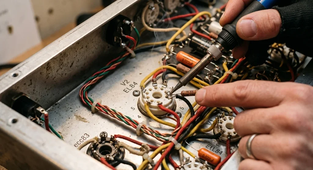
You need reliable EL84 sockets when you repair or build high-performance valve amplifiers. Choosing heavy-duty ceramic chassis-mount models or molded Belton 9-pin Noval sockets directly affects your amp’s thermal performance. For instance, ceramic sockets handle high heat, while Belton sockets maintain firm pin tension over years of tube swaps.
More importantly, beyond hardware selection, proper wiring practices prevent parasitic oscillation and ground hum in your output section. Solder grid stoppers directly onto pin 2 with the shortest leads possible. Mount each screen grid resistor using dedicated chassis tie points to avoid mechanical stress on solder lugs. Always inspect the tube datasheet before soldering. Never use a pin marked with an internal connection as a wiring junction.
Use these schematics and pinout diagrams to wire your EL84 tube socket correctly.
More importantly, orient your ceramic or Belton EL84 socket so the gap between pin 1 and pin 9 points toward your power supply feed. Count pins clockwise from the chassis underside, starting at pin 1 on the right edge of the gap.
-
Pins 1, 6, & 8 (Internal Connections): Leave these terminals empty. Valve manufacturers anchor internal glass supports to these pins. Wiring signal or voltage leads to these points creates short circuits.
-
Pin 2 (Control Grid): Solder a 1.5k ohm grid-stop resistor to this lug. Keep the resistor body close to the socket pin to stop high-frequency oscillation.
-
Pin 3 (Cathode & Suppressor Grid): Connect your cathode bias resistor and bypass capacitor to this pin. Run the return connection to your main ground bus.
-
Pins 4 & 5 (Heater Circuit): Twist two 18-gauge solid copper wires at three turns per inch for your 6.3V AC supply. Push this pair flat against the chassis floor to shield audio signals from hum.
-
Pin 7 (Anode / Plate): Solder the output transformer primary lead to this pin. Route this high-voltage conductor away from sensitive input lines.
-
Pin 9 (Screen Grid): Mount a 1k ohm screen resistor on a separate chassis tie point, then run a short wire to pin 9. Off-socket mounting protects the EL84 socket from excessive heat.
Ceramic vs. Micanite and PCB vs. Chassis-Mount Noval Sockets
At the same time, executing this exact wire dress on your EL84 tube socket stabilizes the output stage and stops self-oscillation. Orient the socket gap toward the power transformer before running any wire. This position creates the shortest path for high-current heater lines while keeping signal wires clear of AC hum fields.
           ( Gap )
       Pin 9     Pin 1
    Pin 8           Pin 2
   Pin 7             Pin 3
    Pin 6           Pin 4
           Pin 5
Follow this physical wiring layout on every 9-pin Belton socket or ceramic chassis-mount socket:
-
Pins 4 & 5 (Heater Line): Strip 1/4 inch of insulation off twisted 18 AWG solid wire. Push conductors straight through lugs 4 and 5 from below. Solder both connections cleanly. Keep the twisted pair flat against the chassis corner.
-
Pin 2 (Grid Stopper Resistor): Solder carbon composition grid stoppers leads through the lug eyelet. Cut the lead short. Keep the resistor body less than 5 millimeters from the pin terminal.
-
Pin 9 (Screen Grid Resistor): Mount a 1k ohm flameproof screen grid resistor directly to pin 9. Anchor the opposite end to an isolated chassis terminal strip. Never use pins 1, 6, or 8 as auxiliary tie points for this connection.
-
Pins 3 & 7 (Cathode & Anode): Route the primary transformer wire straight to pin 7. Wrap the cathode lead through pin 3 before heating the joint.
For example, verify every solder joint visually under bright light. Re-tension lug clips with a thin dental pick if tube pins fit loosely inside ceramic or Micanite sockets.
Recommended Brands: Upgrading to a 9-Pin Belton Socket or Vintage Options
As a result, connecting these terminal points correctly requires a clear top-down visual layout before you heat your soldering iron. Use this visual guide to map out lead routing on a replacement ceramic or 9-pin Belton socket.
                     TOP-DOWN SOCKET LAYOUT
                         Gap (Keyway)
              (Pin 9)                    (Pin 1)
       Screen Resistor (1k Ω)       [NO CONNECTION]

       (Pin 8)                              (Pin 2)
    [NO CONNECTION]                     Grid Stopper Resistor
                                           (<5mm Lead)
        (Pin 7)                             (Pin 3)
      Plate / Anode                      Cathode Lead

         (Pin 6)                          (Pin 4)
      [NO CONNECTION]                  Heater Line (18 AWG)
                        (Pin 5)
                      Heater Line
Molded thermoplastic Belton units feature sturdy, recessed lugs that trap solder cleanly. Consequently, you can thread your leads straight through the lug eyelets without wrapping excess wire.
Follow these strict physical layout rules during socket installation:
-
Input Pin 2: Position carbon composition grid stoppers less than 5 millimeters from the lug. This layout stops high-frequency parasitic oscillation instantly.
-
Screen Pin 9: Mount your flameproof screen grid resistor directly to the terminal tag. Run the source end to a separate chassis terminal strip.
-
Pins 1, 6, and 8: Leave these lugs empty. Factory internal connection wires inside some EL84 tube socket brands contact these pins. Utilizing them as floating tie points creates dangerous short circuits inside your tube amplifier chassis.
Orient the socket keyway gap toward the rear chassis wall. Next, seat the mounting flange flush against the metal cutout. Apply a 40-watt iron to form shiny, concave solder fillets on every completed lug.
EL84 Tube Amplifier Socket Pinout and Wiring Fundamentals
Meanwhile, once you seat the socket body, reference the physical pin arrangement from the bottom chassis perspective before stripping your lead wires. View the 9-pin Belton socket from the lug side with the keyway gap pointing directly toward the rear panel.
          [ Keyway Gap ]
   Pin 9 (Screen)    Pin 1 (IC)
 Pin 8 (IC)            Pin 2 (Control Grid)
 Pin 7 (Plate)         Pin 3 (Cathode / G3)
   Pin 6 (IC)        Pin 4 (Heater)
          Pin 5 (Heater)
Execute your EL84 tube socket lead connections according to these precise spatial standards:
-
Pins 1, 6, and 8: Keep these terminals completely bare. Factory internal connection wires inside many EL84 envelopes utilize these pins. As a result, soldering component leads to these lugs causes destructive high-voltage shorts.
-
Pin 2 (Control Grid): Solder your carbon composition grid stoppers directly to this lug. Keep the resistor body under 5 millimeters from the pin. Consequently, this short lead distance blocks high-frequency RF oscillations instantly.
-
Pin 3 (Cathode / Suppressor): Connect your shared cathode resistor and bypass capacitor parallel branch here. Run the ground side straight to your central chassis power ground point.
-
Pins 4 and 5 (Heater Filament): Dress your 18 AWG tightly twisted heater wires against the metal chassis floor plane. Drop the lead ends vertically at 90-degree angles straight into pins 4 and 5.
-
Pin 7 (Anode / Plate): Attach your output transformer primary wire using 600-volt rated high-temperature wire. Route this lead away from low-level input signal paths to prevent audio feedback.
-
Pin 9 (Screen Grid): Anchor one lead of a 1k ohm flameproof screen grid resistor directly to Pin 9. Solder the supply lead to an isolated chassis terminal strip.
Standard 9-Pin Noval Pinout Identification
Master the physical layout of a 9-pin Belton socket before you apply hot solder to any connection point. First, view the underside of the socket with the wide pin gap oriented straight down at six o’clock. Next, count the pin numbers clockwise starting from Pin 1 on the left side of the gap up to Pin 9 on the right side.
       [Bottom View - Chassis Underside]
               Pin 5 (Heater)
          Pin 4           Pin 6 (IC/NC)
            |               |
    Pin 3 --+               +-- Pin 7 (Anode / Plate)
  (Cathode) |               |
            |   (NOVAL)     |
    Pin 2 --+               +-- Pin 8 (IC/NC)
 (Control Grid)             |
          Pin 1           Pin 9 (Screen Grid)
        (IC/NC)   GAP
               (6 o'clock)
Follow this precise blueprint when wiring the EL84 tube socket stage inside your tube amplifier:
-
Pin 1 (IC/NC): Leave completely empty. Do not use this lug as tie points for surrounding components.
-
Pin 2 (Control Grid): Solder your grid stoppers directly to this terminal. Keep lead lengths under 5 millimeters to eliminate high-frequency RF oscillation.
-
Pin 3 (Cathode/Suppressor): Wire your cathode bias network directly to this lug. Route the ground lead straight to your central chassis ground point.
-
Pins 4 & 5 (Heater Filament): Twist your 18 AWG heater leads tightly together. Lay the pair flat against the chassis floor, then drop the leads vertically into lugs at 90-degree angles.
-
Pin 6 (IC/NC): Leave empty. An internal connection inside many EL84 tube envelopes carries full plate potential to this pin.
-
Pin 7 (Anode/Plate): Route the high-voltage wire from your output transformer directly to this lug. Keep this primary lead away from low-level input signal lines.
-
Pin 8 (IC/NC): Leave empty. Never attach power supply wires or board leads to this terminal.
-
Pin 9 (Screen Grid): Mount a flameproof screen grid resistor directly to this terminal. Keep the lead under 10 millimeters long to maintain complete circuit stability.
Always inspect every solder joint visually and verify resistance to ground with a meter before applying high voltage to the circuit.
Proper Heater Circuit and Screen Grid Resistor Wiring
By contrast, translate those meter readings directly into a functional chassis layout diagram before heating your soldering iron. When you install a 9-pin Belton socket inside a custom tube amplifier, align your physical wiring against this circuit topology:
                  [ +300V B+ Power Rail ]
                             │
                 [ Screen Grid Resistor ]
                             │ 1k Ohm, 5W Flameproof
                             ▼
                         ( Pin 9 )
                            ┌┴┐
                            │ │ EL84 Tube
                            └┬┘
               ( Pin 2 )     │     ( Pin 7 )
  [ Signal ]──[ Grid Stopper ]─┴─────[ OT Primary Lead ]
               5.6k Ohm
                             │
                         ( Pin 3 )
                             │
                   [ Cathode Bias Network ]
                             │
                             ▼
                     [ Chassis Ground ]

     [ 6.3 VAC Heater Wire Pair: 18 AWG Twisted 3 Turns/Inch ]
     ───► Pin 4
     ───► Pin 5 (Lay flat on chassis, drop vertically at 90°)

     [ Unused Pins: NO CONNECTIONS ]
     ─── Pin 1 (IC)  │  Pin 6 (IC)  │  Pin 8 (IC)
Mount your screen grid resistor directly to Pin 9 on the EL84 tube socket. Position the body of this 1k ohm flameproof resistor within 10 millimeters of the terminal lug. Wire your high-voltage supply line directly to the free lead of the resistor. Consequently, this short physical path eliminates high-frequency screen oscillation and protects the tube envelope.
Next, dress your 6.3 VAC heater supply lines using 18 AWG solid copper wire. Twist the heater wire pair tightly at a minimum density of 3 turns per inch. Push the twisted pair flat against the metal chassis floor to shield your signal wires from AC magnetic fields. As a result, dropping the lead ends vertically into Pins 4 and 5 at 90-degree angles stops hum injection into sensitive grid circuits. Never use Pins 1, 6, or 8 as tie points for off-board components.
Can You Use Unused EL84 Socket Pins as Tie Points?
In addition, observe the terminal layout shown above and isolate every internal connection lug before soldering your signal leads. When installing a premium 9-pin Belton socket or ceramic chassis mount in your tube amplifier, route your control grid signal through a dedicated 5.6k ohm grid stopper attached directly to Pin 2. Trim the resistor lead to a maximum length of 5 millimeters to suppress high-frequency parasitic oscillation.
Correct EL84 Socket Wiring Topology:

[ Input Signal ] ─► [ 5.6k Grid Stopper ] ──────► Pin 2 (Control Grid)
[ B+ Screen Node ] ─► [ 1k 5W Resistor ] ────────► Pin 9 (Screen Grid)
[ Pin 3 Cathode ] ──► [ 130R / 25uF Network ] ──► Chassis Ground
[ Pins 1, 6, 8 ] ──► FLOATING / UNCONNECTED (Do NOT use as tie points)
Specifically, as a direct consequence of this strict layout, high voltage remains completely isolated from sensitive grid circuits. Mount a two-lug insulated terminal strip within 20 millimeters of the EL84 tube socket to provide anchor points for off-board power supply nodes.
More importantly, solder your screen grid resistor across Pin 9 and the isolated terminal lug. In contrast to unsafe vintage wiring practices, this mechanical separation prevents short circuits across internal connection points inside the EL84 envelope. Connect Pin 3 directly to your cathode bias network, running the ground lead straight to your main chassis star ground point. Always cross your control grid leads at strict 90-degree angles over AC heater lines to eliminate hum.
Internal Connections (IC) vs. No Connections (NC)
Beyond proper AC heater geometry, enforce absolute separation between signal lines and internal connection pins on your EL84 tube socket. Tube manufacturers utilize internal connection pins as structural support anchors inside the glass envelope. Consequently, these terminal points carry dangerous voltages that destroy control grid stoppers if used as tie points.
EL84 Socket Pin Architecture:

          [Pin 1: IC]     ──── UNUSED (Do Not Cable)
     [Pin 2: Grid]        ──── 5.6k Grid Stopper (≤5mm Lead)
     [Pin 3: Cathode]     ──── Bias Network to Star Ground
   [Pin 4: Heater]        ──── 6.3 VAC (Twisted Pair)
   [Pin 5: Heater]        ──── 6.3 VAC (Twisted Pair)
     [Pin 6: IC]          ──── UNUSED (Do Not Cable)
     [Pin 7: Plate]       ──── Output Transformer Primary
     [Pin 8: IC]          ──── UNUSED (Do Not Cable)
          [Pin 9: Screen] ──── 1k 5W Resistor (≤10mm Lead)
Inspect your 9-pin Belton socket before attaching any passive components. Treat Pins 1, 6, and 8 as active high-voltage nodes at all times. Never solder jump wires or secondary leads across internal connection terminals.
In practice, if your layout requires auxiliary anchor points, install a dedicated two-lug terminal strip nearby. Mount this terminal strip within 15 millimeters of the socket rim. Solder off-board grid stoppers and power supply feed lines directly to insulated turret lugs rather than unused socket lugs. This rigorous layout practice prevents catastrophic high-voltage flashover inside your tube amplifier chassis.
The Risk of Shorting Grid Stoppers on 6BQ5 / EL84 Tubes
Follow this exact physical routing scheme when you construct or upgrade an EL84 tube socket layout.
[Input Signal] ──> [2-Lug Terminal Strip] ──[5.6k Grid Stopper (≤5mm)]──> [Pin 2: Control Grid]
                                                                               │
[Heater Bus 6.3VAC] ──(Tightly Twisted Pair)──[Crosses Pin 2 Wire at 90°]──────┘

[B+ Screen Rail] ──> [Terminal Lug] ──[1k 5W Resistor (≤10mm)]──────────> [Pin 9: Screen Grid]
At the same time, solder the body of your 5.6k ohm grid stopper directly to an off-board terminal lug. Keep the lead running to Pin 2 under 5 millimeters in length. This tight placement stops parasitic oscillations instantly without using internal connection pins as tie points.
Next, elevate your 1k ohm 5-watt screen grid resistor 8 millimeters off the socket base. Solder one lead directly to Pin 9 and attach the input end to your isolated terminal strip. As a result, thermal energy dissipates into the open chassis air instead of damaging the ceramic body.
Route your 6.3 VAC heater wires as a tightly twisted pair along the chassis floor. Pull this pair straight up to Pins 4 and 5 at a sharp perpendicular angle. Keep all heater lines at least 12 millimeters away from the Pin 2 control grid wire. Consequently, you remove AC hum from the signal path before it reaches your power section.
For example, when you install a premium 9-pin Belton socket, verify that every solder joint forms a smooth concave fillet. Trim all excess component leads flush to prevent high-voltage arcing across adjacent terminals in your tube amplifier.
Safe Wiring Alternatives: Turret Boards and Terminal Strips
As a result, isolate your signal path completely from internal connection pins by installing a dedicated three-lug terminal strip adjacent to each EL84 tube socket. Mount the grounding foot of this terminal strip directly to the chassis wall within 15 millimeters of the socket perimeter, Because of this proximity, your component leads stay short while mechanical stress remains off the fragile ceramic socket lugs.
Study the layout diagram below to route high-voltage lines and delicate signal paths safely without utilizing Pins 1, 6, or 8 as structural anchor points:
[B+ Rail (+300V)] ───> [Lug 1: Isolated Strip] ───[1k 5W Resistor]───────> [Pin 9: Screen Grid]
                                                                            │
[Input Signal]   ───> [Lug 2: Isolated Strip] ───[5.6k Grid Stopper]─────> [Pin 2: Control Grid]
                                                                            │
[Chassis Ground] ───> [Lug 3: Grounded Foot]  ───[130R 5W + 50uF Cap]───> [Pin 3: Cathode]
                                                                            │
[6.3 VAC Pair]   ─────────────────(Twisted Pair 90° Cross)──────────────> [Pins 4 & 5: Heaters]
Meanwhile, to execute this layout, solder your incoming B+ supply wire to Lug 1 of the isolated terminal strip. Span your 1k ohm 5-watt screen grid resistor across the gap between Lug 1 and Pin 9 of the 9-pin Belton socket. Keep this resistor body elevated 8 millimeters off the socket surface. As a direct result, heat escapes efficiently into the chassis environment without baking adjacent socket contacts.
Next, attach your grid coupling capacitor to Lug 2 on the terminal strip. Connect your 5.6k ohm grid stoppers from Lug 2 straight to Pin 2 of the EL84 tube socket. Keep this grid stopper lead under 5 millimeters to eliminate RF interference. Finally, join your cathode bias resistor and bypass capacitor in parallel between Lug 3 and Pin 3. Run a dedicated copper wire from Lug 3 to your main central star ground point. This layout guarantees a stable tube amplifier power stage free from catastrophic high-voltage breakdown.
Step-by-Step EL84 Socket Replacement and Upgrades
Execute these final wiring steps directly on your 9-pin Belton socket to lock in operational stability and prevent mechanical failure.
       [ Isolated Lug 1 ] ───[ 1k 5W Screen Resistor ]───> Pin 9 (Screen Grid)
              │
       [ Isolated Lug 2 ] ───[ 5.6k Grid Stopper ]───────> Pin 2 (Control Grid)
              │
       [ Ground Lug 3   ] ───[ 130R 5W + 50uF Cap ]──────> Pin 3 (Cathode)
              │
       [ Central Star Ground Point ]
First, route the 6.3 VAC heater wires as a tight twisted pair along the chassis corner. Keep the twist pitch under 10 millimeters per turn to cancel hum. Bring this twisted pair straight to Pins 4 and 5 at a strict 90-degree angle relative to all signal leads. Consequently, you prevent AC filament ripple from coupling into the high-gain control grid at Pin 2.
Next, inspect the socket lugs before soldering any passive components. Never use Pins 1, 6, or 8 as anchor points or tie points. Tube manufacturers frequently establish an internal connection to these unused pins for structural support during tube manufacturing. As a result, attaching signal or power leads to these pins can inject high voltage straight into tube elements or short out your bias supply.
                   ┌───────── U ─────────┐
                   │   Pin 9   Pin 1     │  <-- Pin 1: DO NOT USE (Internal Conn)
                   │  (Screen)   (IC)    │
                   │                     │
 (Control Grid) -->│ Pin 8       Pin 2   │<-- Pin 2: Grid Stopper Input
   (DO NOT USE)    │  (IC)       (Grid)  │
                   │                     │
     (Cathode) --->│ Pin 7       Pin 3   │<-- Pin 3: Cathode Bias Loop
                   │ (Anode)   (Cathode) │
                   │    Pin 6   Pin 4    │
                   └─────── Pin 5 ───────┘
                       (Heater Loop)
Solder the 5.6k ohm grid stoppers directly to Pin 2 with a lead length under 5 millimeters. Trim all excess component leads flush to avoid accidental arc-over across adjacent pins. In addition, sleeve the raw lead wire in high-temperature fiberglass tubing to prevent shorts against the chassis floor.
Finally, verify the placement of your 1k ohm 5-watt screen grid resistor attached to Pin 9. Maintain an absolute minimum space of 8 millimeters between the ceramic resistor body and the chassis surface. As a direct benefit, air circulates freely around the component and prevents heat damage to your tube amplifier chassis wiring. Rigorously inspect every mechanical joint before applying primary power.
Discharging Capacitors and Removing Vintage Sockets
Verify zero energy storage across all supply rails before desoldering high-voltage connections from an old EL84 tube socket. Clip a 10k ohm 10-watt resistor between the main filter capacitor positive terminals and chassis ground for 30 seconds. Consequently, residual potential drops safely to zero. Confirm residual potential measures under 1 millivolt DC with a calibrated digital multimeter before touching any wiring.
       [ EL84 / 9-Pin Noval Socket Wiring Layout ]

               (Heater)       (Heater)
                Pin 4          Pin 5
                  │              │
    (Cathode) ────┼─ Pin 3    Pin 6 ─┼──── (IC - DO NOT USE)
                  │              │
 (Grid Stopper) ──┼─ Pin 2    Pin 7 ─┼──── (Anode / Plate)
                  │              │
(IC - NO TIE) ────┼─ Pin 1    Pin 8 ─┼──── (IC - DO NOT USE)
                  └────── Pin 9 ──────┘
                     (Screen Grid)
Unbolt the defective socket by removing the two M3 mounting hardware sets. Extract all residual solder from the chassis wire ends using a vacuum desoldering pump. Next, align your replacement 9-pin Belton socket so Pins 4 and 5 face the power transformer side of the chassis. Tighten the socket mounting flange securely to the chassis surface using tooth lock washers to guarantee structural ground continuity.
By contrast, route tightly twisted 18 AWG heater wires directly to Pins 4 and 5. Keep the heater wire pair pressed flat against the chassis floor to suppress hum induction into surrounding audio signal paths.
In addition, connect the incoming signal wire to a 5.6k ohm grid stopper resistor. Solder the resistor body directly to Pin 2 while trimming the active lead length to less than 5 millimeters.
Specifically, as a safety rule, never utilize Pins 1, 6, or 8 as insulated tie points. These terminals maintain internal connections inside many EL84 tube designs. Shorting active circuit traces across these terminals risks immediate tube destruction and power transformer damage.
Attach a 1k ohm 5-watt screen grid resistor across Pin 9. Position the ceramic resistor body exactly 8 millimeters above the socket mounting rim. As a result, air flows freely to prevent heat damage to your tube amplifier chassis wiring.
Position the screen grid resistor, then check your layout against this bottom-view diagram for a standard 9-pin Belton socket.
           ( GAP )
       Pin 9     Pin 1
    Pin 8           Pin 2
   Pin 7             Pin 3
    Pin 6           Pin 4
           Pin 5
More importantly, orient the keyway gap at 12 o’clock. Count the lugs clockwise from the gap while looking into the bottom of the chassis:
-
Signal Lugs: Solder your input signal lead or grid stopper to Pin 2 (Control Grid). Connect your cathode resistor and bypass capacitor network to Pin 3 (Cathode/Suppressor).
-
Heater Lugs: Run your 6.3V filament pair to Pins 4 and 5.
-
High Voltage Lugs: Attach the primary lead from your output transformer to Pin 7 (Anode). Connect your high-voltage screen supply lead to Pin 9 (Screen Grid).
-
Unused Lugs: Pins 1, 6, and 8 connect to internal structural anchors. Leave these terminals empty.
In practice, install spring-loaded retainer clips to prevent vacuum tubes from backing out during cabinet vibration. Bolt the clip brackets to the mounting flange using M3 screws and star lock washers. Stretch the retention springs over the tube base to seat the pins into the socket contacts.
Prepare each wire before soldering. Strip insulation back 3 millimeters. Hook the bare wire through the lug eyelet to create a mechanical bond. Set your soldering station to 370 degrees Celsius. Touch the iron tip to the eyelet and wire for three seconds. Feed 63/37 rosin-core solder into the joint until a shiny, concave fillet covers the junction.
FAQ About el84 sockets
What is the difference between an EL84 and a 6BQ5 tube socket pinout?
At the same time, there is no difference between an EL84 and a 6BQ5 tube socket pinout. European manufacturers used the EL84 designation, while American factories called the exact same design the 6BQ5. Both tubes use a standard nine-pin Noval base with identical pin assignments for the plate, screen, grid, cathode, and heaters. You can swap a 6BQ5 into an EL84 socket without rewiring the amplifier.
For example, before you install a new set, inspect pins one, six, and eight on your amplifier socket. Tube manufacturers label these pins as internal connections, so vintage amplifier builders used them as anchor points for extra resistors or capacitors. Modern replacement tubes connect these internal pins in ways that short-circuit your amp if a component touches them.
What happens if you attach component leads to pins 1, 6, or 8?
Connecting component leads to pins 1, 6, or 8 risks severe circuit damage and ruined tubes. Socket diagrams label these pins as unused or internal connections, but tube manufacturers attach structural wires to them inside the glass. When you solder a component to pin 1, 6, or 8, you route high voltage into wrong parts of the circuit.
Treat pins 1, 6, and 8 as live connections. Skip these pins when you mount extra parts. If you anchor a grid stopper resistor to pin 1, a Sovtek EL84 works, but a JJ EL84 shorts high voltage into your input signal. Keep these three pins empty and use separate terminal strips for extra components.
How do I re-tension loose contacts on a 9-pin EL84 socket?
Unplug your amplifier and discharge the power supply capacitors before you touch the chassis. Insert a fine dental pick or a small jeweler’s screwdriver into the outer edge of the socket hole. Push the metal spring clip toward the center of the opening. Repeat this motion on all nine locations to restore a tight grip.
Test your work by pushing a spare EL84 tube into the socket. You need a firm grip on every pin. If you feel no resistance, repeat the process on the loose contacts until the socket holds the tube pins tight.