
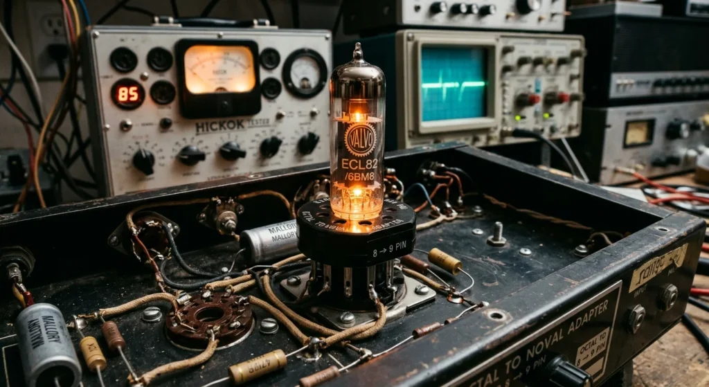
You need the right tube socket adapter when swapping audio valves or altering circuit designs. If you install cheap conversion sockets, you risk contact resistance, unwanted hum, and severe thermal stress. You must evaluate pin alignment, insulator materials, and solder joints before bench testing your amplifier. Ceramic tube sockets withstand higher operating temperatures than standard phenolic plastics. As a result, choosing ceramic build quality prevents pin slop and electrical arcing under high plate voltages.
When you adapt an octal 8-pin socket to a noval 9-pin socket, you need exact pinout accuracy and tight tolerances. You cannot afford loose contact sleeves on high-bias vacuum tube sockets. Furthermore, solid copper contacts maintain constant spring tension against the valve pins during thermal expansion. I evaluated contact resistance, heat resistance, and physical build quality across top conversion models. You will learn how to select reliable adapters that preserve original circuit performance and protect your gear.
Understanding Vacuum Tube Sockets, Adapter Types, and Core Applications
To optimize your tube socket adapter selection, inspect the structural integrity of the base materials before applying high DC plate voltages. Standard phenolic adapters soften under heavy thermal loads. Consequently, the pin receptacles expand and lose clamping pressure against the valve pins. You cannot allow loose pin connections on high-power audio circuits. Loose pins generate intense arcing, which destroys your valve bases and introduces parasitic oscillation.
Instead, specify high-grade ceramic tube sockets with silver-plated or solid copper contacts. As a result, your connection maintains low contact resistance even during prolonged bias testing. Always verify that chassis mount adapters include rigid mounting flanges. If you run unshielded noval 9-pin socket setups near sensitive grid lines, microphonic hum will leak into your signal path. To stop stray interference, install grounding rings compatible with metallic tube shields.
When converting an octal 8-pin socket configuration down to smaller valve bases, inspect the internal jumper wiring. Poorly soldered connections inside cheap conversion adapters degrade under continuous heat. Consequently, cold solder joints fail under high filament current draws and drop your heater voltage below operational limits. Check every pin joint on your bench meter before plugging an adapter into your amplifier chassis.
Audio Converters vs. Structural Tube Mounting Systems
After you complete meter verification, evaluate whether your tube socket adapter meets high-voltage signal demands or physical structural needs. Audio converters route high plate voltages and delicate signal currents, while structural frame clamps secure mechanical tubing on equipment frames.
You must not substitute structural mounting clamps for an electrical chassis mount. Industrial pipe fittings lack dielectric insulation, which causes immediate high-voltage short circuits across your frame. When you optimize an audio conversion setup, choose ceramic tube sockets anchored inside rigid metal housings. This construction prevents mechanical forces from flexing your internal amplifier wiring.
If your setup converts an octal 8-pin socket down to a noval 9-pin socket, measure vertical clearance inside your enclosure. The added height of a conversion socket increases mechanical leverage on the lower receptacle. Consequently, inserting tight-fitting valve pins into elevated adapters bends chassis contacts and fractures solder joints. Mount physical support brackets directly to your chassis panel whenever you install tall conversion hardware.
Primary Mechanical and Electrical Considerations Before Purchase
Beyond physical chassis support, you must inspect the electrical specifications and contact metallurgy of a tube socket adapter before purchasing it. High heater currents quickly heat up inferior contact spring clips. Consequently, poor spring tension causes voltage drops across filament pins and starves your valves of proper operating power.
Always choose ceramic tube sockets built with heavy-duty phosphor bronze or beryllium copper contacts. These metals withstand repeated thermal expansion cycles without losing retention force. As a result, your adapter pins stay tight and maintain low electrical resistance over thousands of operating hours. When you run high plate voltages above 400 volts, cheap phenolic base adapters arc across adjacent terminals. Insist on thick ceramic insulation to prevent catastrophic electrical breakdown.
For sensitive preamplifier stages converting down to a noval 9-pin socket, verify that the adapter housing accepts grounded metallic tube shields. External magnetic fields induce hum directly into unshielded signal paths. Therefore, installing grounded tube shields isolates high-gain grid lines from ambient interference. Inspect pin retention force manually before you secure any adapter into a permanent chassis mount setup. Tight pins prevent microphonic noise and keep continuous power flowing to your circuit.
Audio Vacuum Tube Socket Adapters and Pin Conversions
Beyond checking pin retention force, audit internal wire gauges inside your tube socket adapter before installing high-draw power valves. Cheap commercial units often use thin 24 AWG copper-clad aluminum wires that drop heater voltage under load.
Always select a tube socket adapter built with solid copper leads rated for at least 3 amps. As a result, your tube heaters receive stable operational voltage without overheating the internal socket matrix.
Inspect the insulator base assembly for chemical purity and clearance across adjacent pins. When adapting an octal 8-pin socket to a noval 9-pin socket layout, high plate voltages sit close to sensitive grid pins, Because of this tight pin spacing, arc-over occurs if flux residue remains on the base matrix. Clean all internal ceramic tube sockets thoroughly with isopropyl alcohol before final installation.
Verify vertical chassis clearance when adding tall adapter assemblies to audio enclosures. Extended socket height creates mechanical leverage against original chassis mounts. Consequently, continuous vibration weakens soldered connections and damages vintage vacuum tube sockets over time. Attach rigid external support brackets whenever your adapter assembly exceeds two inches in total height. Finally, double-check that aluminum tube shields lock firmly onto grounding rings to suppress ambient hum across high-gain signal lines.
Converting Octal 8-Pin Socket to Noval 9-Pin Socket Configurations
Align the adapter’s aluminum tube shields directly with the chassis lug to establish a low-impedance ground path. As a result, stray RF interference bypasses the grid wiring and dumps safely into the chassis ground plane.
Measure contact resistance across every pin transition from the octal 8-pin socket base to the top noval 9-pin socket receiver using a low-resistance multimeter. High contact resistance creates localized heating during high-current operation. Consequently, thermal cycling oxidizes metal contact surfaces and degrades signal transfer on sensitive grid lines.
Test dielectric insulation resistance between adjacent pin contacts on the noval 9-pin socket with a 500V DC megohmmeter. Tight pin spacing on noval sockets leaves little margin for voltage clearance across high plate potentials. Therefore, verifying dielectric integrity prevents high-voltage arc-over before you energize the amplifier stage.
Inspect retention spring tension on individual ceramic tube sockets using a non-conductive tension probe. Weak spring clips allow physical movement of the vacuum tube pins inside contact barrels. Over time, physical movement under thermal expansion breaks electrical contact and generates static noise.
Confirm that internal adapter jumper wires use high-temperature sleeving over solid-core copper leads. Uninsulated jumper wires inside compact adapter shells short out under chassis vibration. Ultimately, proper wire routing protects delicate preamplifier circuits from catastrophic high-voltage short circuits.
Critical Electrical Factors: DC Heater Circuits and Plate Voltage Limits
Measure the DC voltage drop across the heater terminals of your tube socket adapter under full filament load. Insufficient conductor mass inside cheap adapters drops heater voltage below nominal operational limits. As a result, starvation of the cathode emission layer lowers amplifier output power and raises total harmonic distortion.
Verify that internal DC heater jumpers maintain at least 18 AWG solid copper wire on high-current filament lines. Thin internal wiring heats up rapidly under continuous three-amp filament draws. Therefore, localized heating weakens spring contact tension inside the noval 9-pin socket assembly and causes intermittent heater supply failures.
Check dielectric clearance between high-voltage plate pins and nearby chassis mount hardware during adapter installation. Stacking socket adapters elevates tube contacts closer to grounded metal enclosures. Consequently, high plate potential arc-overs jump the air gap and destroy delicate grid resistors.
Select high-grade ceramic tube sockets for adapter builds operating above 450V DC plate potential. Molded plastic bases absorb atmospheric moisture over prolonged thermal cycles. For this reason, reduced surface insulation resistance creates carbon tracking between adjacent octal 8-pin socket terminals.
Ground all external tube shields directly to the amplifier chassis ground point. Floating metallic shields pick up ambient electromagnetic interference. As a result, stray noise couples directly into high-impedance control grid circuits.
Amplifier Circuit Incompatibilities and Pinout Safety
Inspect control grid pin mappings on the tube socket adapter before installing non-identical substitution tubes. Pin assignment errors feed high DC plate voltages straight into low-voltage grid circuits. As a result, sensitive preamplifier stages short out instantly and destroy grid-stopper resistors.
Trace internal pin interconnections between the octal 8-pin socket base and the top noval 9-pin socket receiver. Pentodes often tie pin 1 internally to the metal envelope, whereas beam power tubes leave pin 1 unconnected. Therefore, mismatched pin jumpers bridge suppressor grids directly to high-voltage screen supply lines.
Verify cathode resistor wattage ratings when adapting high-transconductance pentodes to existing circuits. Lower internal plate resistance pulls significantly higher idle bias currents through the adapter contacts. Consequently, standard cathode bias components overheat and drift out of operating tolerance.
Isolate unused pin terminals inside the adapter housing using high-dielectric tubing. Floating socket tabs flex and touch adjacent chassis mount hardware under heavy mechanical insertion force. For this reason, structural contact creates direct short circuits across output transformer windings.
Structural and Medical Equipment Tube Socket Adapters
Inspect physical pin retention force on both octal 8-pin socket and noval 9-pin socket adapters prior to mechanical integration. Loose contact spring clips increase pin contact resistance during sustained continuous operation. Consequently, localized thermal energy degrades surface plating and causes intermittent signal loss.
Select ceramic tube sockets with heavy-duty metal retention springs for all chassis mount configurations. Synthetic resin bases soften and deform under high operating temperatures near output power tubes. Therefore, mechanical structural deflection misaligns pin terminals and cracks glass envelope seals.
Measure dielectric isolation resistance across adjacent pins with a megohmmeter before applying operational voltages. Atmospheric moisture absorption and solder flux residue build up conductive leakage paths across the adapter housing. As a result, high plate DC potentials arc across tight mechanical pin gaps.
Torque chassis mount hardware to exact manufacturer specifications using calibrated torque drivers. Over-tightening chassis screws deforms structural mounting flanges and fractures brittle ceramic bodies. For this reason, mechanical stress fractures cause sudden structural adapter failure during equipment transportation.
Install grounded aluminum tube shields over small noval 9-pin socket adapter assemblies. Stray electromagnetic fields penetrate unshielded glass envelopes in sensitive monitoring equipment. Consequently, external radio frequency interference pollutes low-level signal processing channels.
Wheelchair Frame Clamps and Custom Base Unit Specifications
Inspect clamp interface dimensions on custom base units prior to securing chassis mount tube socket adapter hardware. Mismatched tubing diameters apply non-uniform clamping pressure across structural mounting flanges. As a result, physical shear stresses fracture the rigid base housing during equipment movement.
Verify the mechanical load rating of steel chassis mount brackets when mounting heavy adapter assemblies onto dynamic wheelchair frames. Excessive structural vibration fatigue loosens unlatched retention hardware over continuous mobile operation. Consequently, the entire tube socket adapter shifts out of alignment and breaks internal wiring connections.
Apply medium-strength threadlocking fluid to all frame clamp fasteners during final assembly. Constant frame impacts back out standard threaded bolts from un-torqued mounting blocks. Therefore, loose hardware degrades mechanical grounding paths and introduces intermittent signal faults.
Maintain explicit thermal clearance around high-power tube socket adapters installed in enclosed wheelchair base units. Restricted airflow traps operational heat within surrounding plastic frame clamps and degrades adjacent wire insulation. For this reason, thermal buildup causes structural mounting failures and creates high-voltage breakdown hazards.
Tube Diameter Standards: 10mm, 16mm, and M3D Modular System Integration
Measure external frame tubing or component sleeves with digital calipers prior to mounting 10mm or 16mm tube socket adapter assemblies. Mismatched collar tolerances exert uneven clamping force onto fragile ceramic tube sockets or modular aluminum frames. As a result, point-stress concentrations fracture the rigid socket bodies during torque application.
Align the internal keyways of the M3D modular system interface precisely before tightening chassis mount fasteners. Forcing non-aligned modular adapters distorts internal socket spring contacts and misaligns pins when converting between octal 8-pin socket and noval 9-pin socket footprints. Consequently, poor pin retention increases contact resistance and generates destructive thermal loads.
Install grounded metal tube shields onto dynamic 16mm modular mount blocks during high-vibration operations. Unshielded glass envelopes vibrate against external structural clamps without adequate mechanical isolation and shielding. Therefore, mechanical chatter cracks the envelope vacuum seal and destroys the tube.
Verify the grounding continuity across all metal chassis mount adapters using a calibrated digital multimeter. High contact impedance along the grounding path leaves sensitive circuit paths vulnerable to electromagnetic interference. For this reason, ungrounded adapter housings introduce severe signal noise into surrounding control systems.
Technical Specifications and Selection Matrix
Systematically evaluate the structural and electrical metrics of your tube socket adapter to eliminate signal noise and mechanical degradation. Select spring-loaded beryllium copper contacts inside the adapter body to ensure stable contact resistance over repeated thermal cycles. When converting an octal 8-pin socket interface to a noval 9-pin socket footprint, keep pin insertion force below 15 Newtons. Excessive force permanently deforms internal spring clips inside ceramic tube sockets. As a result, loosened contact jaws create intermittent open circuits during high-power operation.
Measure physical clearance for all surface-mount and chassis mount designs before final torque application. Dynamic load applications require spring-loaded tube shields to lock the glass envelope against structural vibration. Unshielded assemblies allow lateral tube movement under high mechanical load. Consequently, mechanical chatter causes severe microphonic distortion and stresses the glass seal.
Verify dielectric breakdown voltage limits on adapter insulating substrates during high-voltage bench testing. High plate voltages degrade low-grade phenolic resin, creating carbon tracking paths between adjacent pins. For this reason, high-voltage vacuum tube sockets and adapters require ceramic or PTFE insulation matrices to ensure operational safety.
Comparing Electrical vs. Mechanical Tube Adapter Characteristics
Selecting the correct insulating material directly dictates both mechanical retention force and electrical breakdown limits during continuous operation. You must evaluate both dielectric strength and physical clamping force when selecting a tube socket adapter for high-reliability systems. PTFE matrices lower pin-to-pin parasitic capacitance, while ceramic bases withstand higher operating temperatures without dimensional warping.
In high-current heater circuits, electrical conductors generate thermal energy that expands the pin contacts. Standard brass spring clips relax under this thermal load, which increases contact resistance across the pins. Consequently, oxidation accelerates along the pin interface and creates localized thermal runaway.
For structural reliability, you must secure heavy chassis mount adapters with dedicated mounting flanges rather than relying on socket pins for mechanical support. Converting an octal 8-pin socket to a noval 9-pin socket shifts the mechanical center of gravity upward. This altered center of mass increases bending moments on the original socket pins during mechanical vibration. As a result, unsupported socket adapters shear off contact lugs and crack the underlying ceramic chassis.
High-frequency audio and RF circuits require short lead routing inside the adapter body to minimize stray inductance. Unshielded wiring runs allow electromagnetic noise to couple directly into high-impedance grid connections. For this reason, systems operating in high-EMI environments require fully grounded metal adapter housings and spring-loaded tube shields to isolate sensitive signal paths.
Ceramic Tube Sockets: Materials, Contact Resistance, and Structural Load Capacities
You must select high-grade steatite ceramic tube sockets to maintain structural rigidity when spring-loaded tube shields exert continuous downward pressure on the assembly. Standard porcelain substrates contain high concentrations of silicate impurities. These impurities lower dielectric strength under elevated operating temperatures. Consequently, high plate voltages cause localized breakdown and form conductive carbon tracking paths across the socket face.
To optimize electrical conductivity in a high-current tube socket adapter, engineers specify silver-plated beryllium copper contacts over standard brass. Lower-grade spring alloys yield rapidly under combined thermal expansion and insertion cycles. As a result, contact retention force drops below acceptable operational thresholds, which increases contact resistance and accelerates thermal degradation along the pin interface. High-grade spring contacts maintain at least 1.5 Newtons of continuous retention force across maximum operating temperature ranges.
Heavy structural loads require specialized mechanical anchoring protocols. Securing a chassis mount ceramic socket body directly against a steel enclosure creates severe stress risers around the mounting holes. For this reason, you must install mechanical isolation washers and torque fasteners to a maximum limit of 0.5 Nm. This mechanical assembly practice prevents micro-cracking in the ceramic body while protecting sensitive vacuum tube sockets from destructive chassis vibration.
Installation Protocols and Best Practices
Damping these chassis vibrations requires proper socket orientation and structural clearance around the adapter body. Converting an octal 8-pin socket to a noval 9-pin socket configuration increases mechanical leverage against the chassis mount points. Consequently, technicians must align the socket keyway precisely with the chassis center line to balance lateral forces during tube insertion.
Adapters elevate the tube above the original mounting plane, which alters airflow and restricts thermal dissipation. Installing aluminum tube shields over noval glass envelopes traps heat if you do not maintain an active cooling path. As a result, thermal stress builds around the base pins, softening solder joints and degrading dielectric insulation over extended operating cycles. You must verify that surrounding components maintain at least 15 millimeters of clearance to allow passive convection.
High insertion forces on misaligned pins bend socket contacts and ruin spring retention force. You should inspect pin straightness with an alignment gauge before pressing any tube socket adapter into place. For this reason, technicians must apply a dry, non-conductive lubricant to the pin contacts during initial bench assembly. Proper pin engagement reduces insertion friction, prevents contact displacement, and extends the operational service life of ceramic tube sockets and primary vacuum tube sockets.
Safe Pin Alignment and Thermal Dissipation for Amp Tube Converters
Applying these lubrication and alignment steps ensures your adapter interface maintains low contact resistance over multiple heat cycles. As a result, you prevent high resistance points that cause localized voltage drops across high-current filament pins. When you retrofit an octal 8-pin socket to accept a noval 9-pin socket converter, you must measure physical clearance above the chassis mount surface. Consequently, you avoid trapping convective heat against sensitive coupling capacitors placed directly beneath the chassis base.
Installing vented tube shields over small-signal envelopes helps divert radiant heat away from adjacent components. For this reason, technicians must measure chassis skin temperature during a full-power 30-minute burn-in test. If skin temperatures exceed 60 degrees Celsius, you must increase passive venting or remove external shield covers. Inspecting contact tension with a retention gauge confirms that each pin maintains at least 1.5 Newtons of clamping force.
Mechanical Torque Settings and Modular Tube Socket Assembly
You verify overall mechanical stability by torquing hardware to precise engineering standards after confirming pin tension. Fasteners on a heavy chassis mount assembly require M3 stainless hardware fitted with split lock washers. As a result, you prevent operational vibration from loosening the mounting hardware over extended runtime.
Modular ceramic tube sockets demand incremental cross-pattern tightening to equalize structural stress across the substrate. For this reason, you must apply torque in 0.1 Nm steps using a calibrated torque screwdriver. Threading an octal 8-pin socket adapter base into a modular chassis flange requires nylon shoulder washers beneath the screw heads. Consequently, you isolate the metal chassis from stray ground paths while securing the adapter baseplate.
Modular adapters converting an octal layout to a noval 9-pin socket format must lie flat against the chassis plane. Any bending of the adapter mounting flange shifts internal contact pins out of axial alignment during tube insertion. As a result, strict torque monitoring ensures low mechanical strain and extends the service life of every tube socket adapter in your system.
FAQ About tube sockets adapter
Can I use a tube socket adapter without modifying my amplifier’s internal wiring?
Yes, you plug the adapter into your amplifier’s existing socket and insert the new tube into the top. Manufacturers design these adapters to reroute pin connections, so you keep your amplifier’s internal wiring stock. You test different tube types without touching a soldering iron.
You must match the electrical limits of your new tube. For example, when you use an adapter to run EL34 power tubes in place of 6L6 tubes, you check your transformer’s heater current draw and reset the bias. Confirm your power transformer supplies enough current before you flip the power switch.
What happens if I connect a 6.3V heater tube adapter to a 12.6V heater circuit?
You burn out the vacuum tube filament in seconds when you connect a 6.3-volt tube adapter to a 12.6-volt circuit. You send double the intended voltage to the heater, which forces four times the design heat through the wire inside the glass shell. You see a bright white flash from the top, and your tube stops working.
You can protect your gear by measuring the socket voltage with a digital multimeter before inserting your adapter. If you run a dual-filament 12AX7 tube on a 6.3-volt supply, you need an adapter that connects pins 4 and 5 together to pin 9.
How do I determine the correct tube socket adapter size for custom frame mounting?
You select the correct adapter size by taking two physical measurements with a digital caliper. First, measure the outside diameter of your frame tube. Second, measure the inside diameter of the receiving socket. You need an adapter with an inside diameter that fits your frame tube and an outside diameter that matches the socket.
If your frame uses a 1-inch outer diameter tube and your mounting socket has a 1.25-inch inner diameter, buy an adapter with a 1-inch inner diameter and a 1.25-inch outer diameter. Measure your actual metal frame instead of relying on manufacturer charts, because powder coating and paint add extra thickness that ruins a tight fit.