
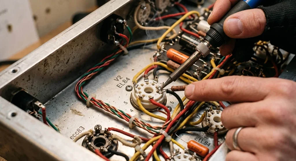
This EL84 pinout diagram shows the standard nine-pin Noval base used by the EL84 (6BQ5). From the bottom of the socket, looking at its solder lugs, pin 2 is the control grid, pin 3 is the cathode and suppressor grid, pins 4 and 5 are the heater, pin 7 is the plate, and pin 9 is the screen grid. Pins 1, 6, and 8 are not general-purpose connection points. The JJ Electronic EL84/6BQ5 data sheet and an original Philips EL84 data sheet provide the tube-side references.
Safety boundary: This is a pin-identification guide, not a complete amplifier schematic or a procedure for working inside an amplifier. Filter capacitors can retain dangerous charge after the unit is unplugged. Internal wiring, testing, and socket replacement belong with a technician trained to verify that the circuit is safe to touch. Amplified Parts’ tube-amplifier safety guidance explains that risk.
EL84 pinout at a glance
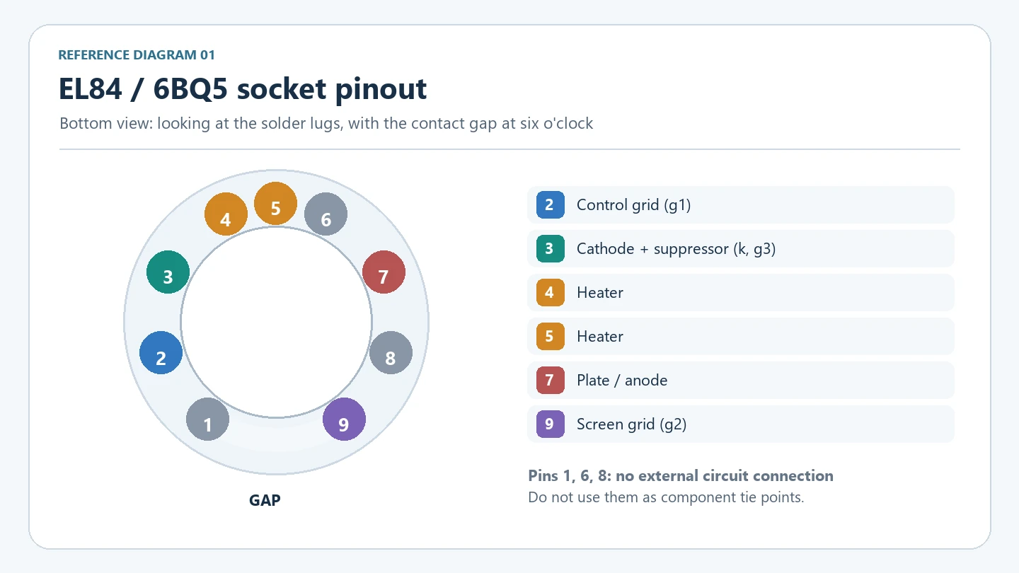
The diagram shows the socket from below, with the gap between pins 1 and 9 at six o’clock. It identifies tube electrodes; it does not specify resistor values or a grounding scheme.
| Pin | EL84 / 6BQ5 function | What to check in the amplifier |
|---|---|---|
| 1 | Unassigned or internally connected, depending on tube maker | Keep out of the external circuit; do not use as a tie point. |
| 2 | Control grid (g1) | Trace the signal and any grid network against the amplifier schematic. |
| 3 | Cathode and suppressor grid (k, g3) | Trace the cathode or bias network; do not assume a direct chassis-ground connection. |
| 4, 5 | Heater | Confirm the specified heater supply and its reference scheme. |
| 6 | Unassigned or internally connected, depending on tube maker | Keep out of the external circuit; do not use as a tie point. |
| 7 | Plate / anode | In a conventional transformer-coupled output stage, trace the output-transformer primary connection. |
| 8 | Internal connection on the cited JJ and Philips sheets | Keep out of the external circuit; do not use as a tie point. |
| 9 | Screen grid (g2) | Trace the screen supply and any series component specified by the amplifier schematic. |
The JJ sheet specifies a 6.3 V, 0.760 A heater for its EL84. That is a tube rating, not permission to copy the rest of one amplifier’s power-supply design into another. Check the exact tube data sheet and the amplifier service information before selecting parts or making a substitution.
Which side of the socket are you looking at?
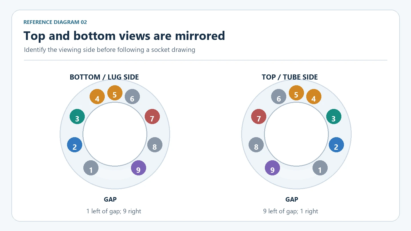
The wide gap separates pins 1 and 9. With that gap at six o’clock, pin 1 sits to the left in the bottom solder-lug view and to the right in the top tube-entry view. The numbering is mirrored because the viewing side changed. A nine-pin socket assembly manual from Amplified Parts also warns that pin positions relative to mounting holes can vary; use the contact gap and the socket’s markings, not the screw holes, to identify the pins.
Before tracing a wire, mark the side shown by your drawing and find the physical gap on the actual socket. Some sockets have molded pin numbers that make this easier. Do not assume that the gap must point toward the power transformer, rear panel, or any other chassis feature: its mounting orientation is a layout choice, while the pin numbers stay fixed relative to the gap.
How the socket connections relate to the circuit
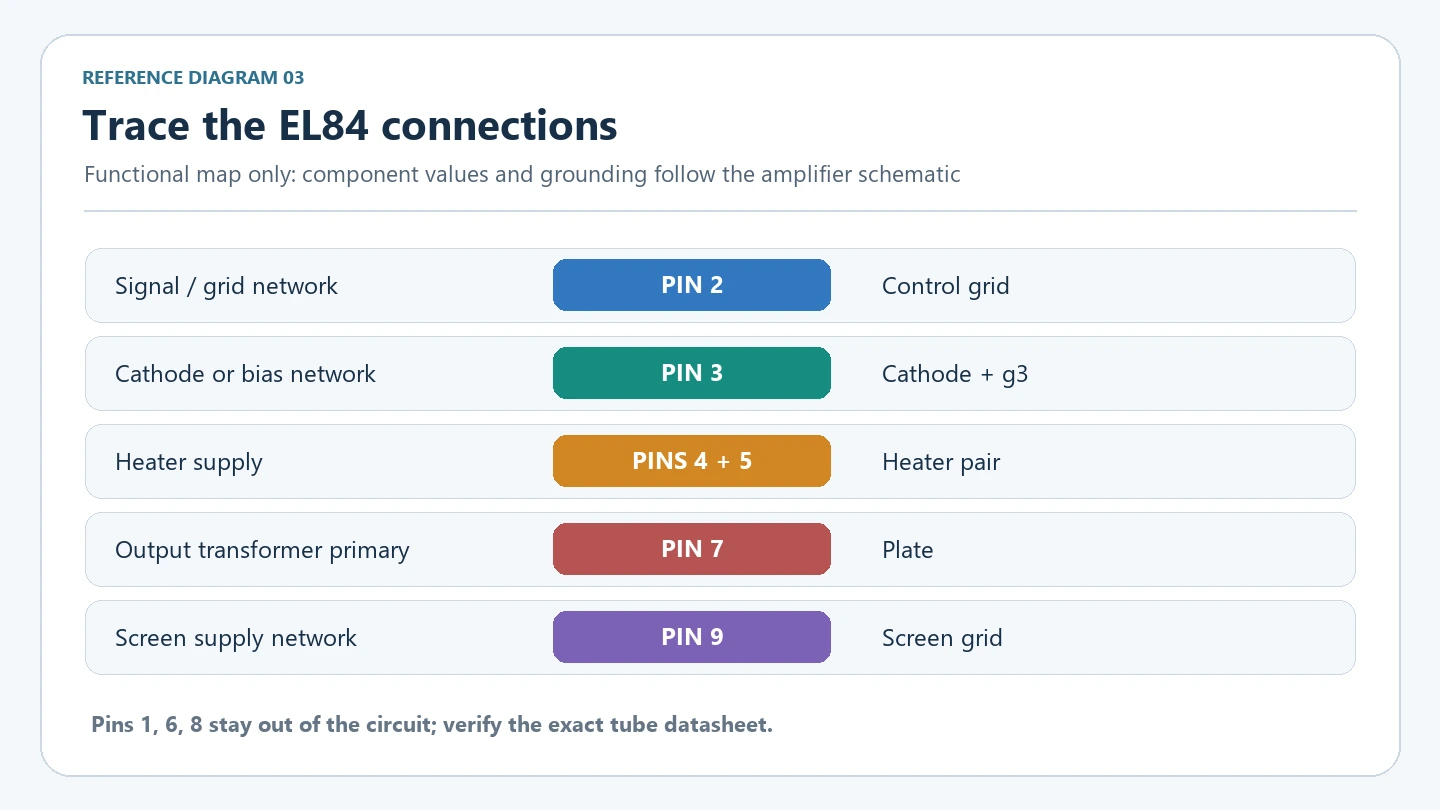
The pinout identifies where each tube electrode is. The amplifier schematic determines what connects to it:
- Pin 2, control grid: The incoming drive reaches this pin through the circuit’s grid network. If that design uses a grid-stopper resistor, its connection near the grid is a layout consideration; neither its resistance nor an exact lead-length limit follows from the EL84 pinout alone.
- Pin 3, cathode and suppressor grid: A cathode-biased stage may use a resistor and bypass capacitor here. Other bias arrangements differ. Follow the actual circuit rather than wiring this pin directly to chassis by default.
- Pins 4 and 5, heater: These are the heater terminals. Heater routing and referencing are part of the amplifier’s hum-control design; a pinout cannot prescribe one wire gauge, twist rate, or ground point for every build.
- Pin 7, plate: In many audio output stages it connects to an output-transformer primary. The transformer, insulation, and routing must match the amplifier design.
- Pin 9, screen grid: The screen supply may include a resistor or other components. Use the schematic and the component’s electrical and thermal ratings; a fixed “1 kΩ, 5 W” rule is not a property of the tube socket.
This distinction matters when repairing an existing amplifier. Copying a photographed socket can reproduce an undocumented modification or a wiring error. Trace each connection to the correct schematic revision and compare it with the tube maker’s pin diagram before a technician returns the unit to service.
Why pins 1, 6, and 8 are poor tie points
The Philips EL84 sheet marks pins 1, 6, and 8 as internal connections. The current JJ EL84/6BQ5 sheet leaves 1 and 6 without external electrode functions and marks 8 as internally connected. That difference is enough reason not to treat any of the three socket lugs as a spare insulated terminal. An amplifier wired to rely on a particular tube’s unused pin can behave differently with another maker’s tube.
If a circuit needs a connection point, its designer or repair technician should provide an appropriate insulated terminal or board pad. The socket pinout by itself does not establish a safe substitute.
Choosing a replacement nine-pin socket
An EL84 and a 12AX7 both fit a nine-pin Noval socket, but their electrical pin functions differ. A mechanically compatible socket is not a prewired adapter. For a replacement, match the original mounting style, chassis cutout or PCB footprint, terminal clearance, retainer arrangement, and the temperature and electrical ratings of the part. Compare the actual product dimensions with the amplifier before ordering.
The CaryElectronic nine-pin socket category shows PCB and chassis-mount options. A ceramic body, molded body, or plated contact is not a universal guarantee of better sound or a cure for hum. Contact condition, mechanical fit, and the surrounding circuit are more relevant to a repair decision. If the issue is intermittent contact rather than a proven tube failure, the site’s socket-fault guide provides symptoms and selection considerations.
A technician’s pre-power checklist
This checklist describes review points, not an energized test procedure:
- Confirm the amplifier model and the correct schematic revision.
- Confirm the intended EL84/6BQ5 type and the chosen maker’s data sheet.
- Identify the socket’s viewing side, gap, and pin numbering.
- Trace each used lug to its circuit node; keep pins 1, 6, and 8 out of the external circuit.
- Inspect mechanical mounting, terminal clearance, insulation, and solder joints.
- Complete the amplifier maker’s safety and commissioning checks with appropriate training and equipment.
Changing power tubes can also raise a bias question, which the pinout cannot answer. See when new power tubes need bias checking for the circuit-dependent distinction.
FAQ
Are EL84 and 6BQ5 pinouts the same?
Yes. JJ identifies the tube as EL84 / 6BQ5 on one data sheet, with the same working-electrode pin assignments. Compatibility with a particular amplifier still depends on that amplifier’s specified tube type and operating conditions, so verify the model rather than inferring suitability from the socket shape alone.
Can I use pins 1, 6, or 8 to anchor a resistor?
Do not assume they are isolated. The cited maker sheets either leave them unassigned or mark them as internal connections. Use a separate connection point specified by the circuit design.
Does the EL84 pinout tell me which grid or screen resistor to buy?
No. It tells you that the control grid is on pin 2 and the screen grid is on pin 9. Component values, power ratings, placement, and grounding come from the amplifier schematic and the tube’s operating limits.
Why do two EL84 socket diagrams appear reversed?
One may show the tube-entry side and the other the solder-lug side. Align the gap between pins 1 and 9 and check the view label before comparing them.
Final takeaway
Use the bottom-view pin diagram to identify the lug, the tube maker’s data sheet to confirm the electrode, and the amplifier schematic to determine the connection. Keeping those three references separate is the safest way to avoid a mirrored pinout or a copied, circuit-specific wiring value.