
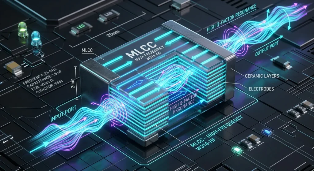
More importantly, selecting high frequency capacitors requires balancing low Equivalent Series Resistance against high Self-Resonant Frequency. As operating frequencies push past 5 GHz, improper component selection causes signal loss and thermal failures.
In practice, modern RF power amplifiers demand Surface Mount Multilayer Ceramic Chip Capacitors (MLCC) built for Ultra High Q performance. When you evaluate Low ESR components, parasitic inductance dictates your usable frequency range. Compact ceramic footprints minimize unwanted ESL and shift resonance points into microwave bands. For high-output transmitters, specialized RF Power Capacitors handle heavy RF currents without drifting off target value under load.
Beyond raw datasheet specs, you need verified S-parameter files and CAD models to validate your board layout. Consequently, this selection guide compares leading manufacturer series across key RF metrics like Q factor and thermal resistance. Use these technical specifications to choose the correct component for your circuit.
Critical Electrical Parameters for High Frequency Capacitors
At the same time, you must quantify how parasitic elements alter component behavior at microwave frequencies. Equivalent Series Resistance (ESR) generates thermal dissipation that damages your power amplifier matching network. Simultaneously, Equivalent Series Inductance (ESL) creates a parasitic loop with nominal capacitance. This interaction defines the Self-Resonant Frequency (SRF) of the component.
Above the SRF, your capacitor turns inductive and disrupts impedance transformation networks. As a result, you must select Surface Mount devices with minimal terminal geometry to suppress ESL. Choosing Low ESR components keeps RF insertion loss below 0.1 dB across passive matching networks.
Low ESR, Low ESL, and Self-Resonant Frequency (SRF)
For example, to calculate the operational limit of your network, evaluate the series combination of parasitic inductance and nominal capacitance. The frequency calculation uses the standard formula:
fSRF = \frac1{2\pi \sqrt{LESL \cdot Cnom}}
Because parasitic inductance drops as component length decreases, small 0402 or 0201 Surface Mount Multilayer Ceramic Chip Capacitors (MLCC)—such as the Murata GJM series or KEMET HiQ-CBR line—push the SRF past 10 GHz. Consequently, reducing terminal spacing suppresses LESL down to sub-nanohenry levels between 0.2 nH and 0.4 nH.
When you operate your circuit at the SRF, capacitive reactance cancels inductive reactance. As a result, the component acts purely resistive at this point. To maintain predictable matching below this threshold, select components with an SRF at least 20% above your maximum working frequency.
As a result, for power amplifiers, Low ESR values directly control heat buildup. You calculate total dissipation using the formula Ploss = IRF^2 \cdot ESR. Furthermore, choosing dielectric formulations with milliohm-level ESR prevents power attenuation. Ultra High Q values over 1000 at 1 GHz indicate minimal thermal loss, preserving amplifier power output across the entire band.
Ultra High Q Factor and Class 1 Ceramic Dielectrics
To maintain these Ultra High Q values across broad thermal ranges, you must select Class 1 Ceramic dielectrics like C0G or NP0, Because Class 1 materials use non-ferroelectric formulations, they exhibit linear temperature coefficients near 0 ±30 ppm/°C. Consequently, your circuit avoids capacitance drift during high-power RF transmit bursts.
When you design high-frequency matching networks, specify Multilayer Ceramic Chip Capacitors (MLCC) built with low-loss porcelain formulations, such as the Kyocera AVX / ATC 100B series or Johanson Technology S42E series. Standard Class 2 dielectrics like X7R suffer from severe voltage coefficient degradation and high dielectric absorption. As a result, Class 2 components introduce signal distortion and thermal runaway in high-RF fields.
Meanwhile, you calculate Q as the direct inverse of the dissipation factor (Q = \frac1DF). Select Surface Mount RF components that maintain Low ESR across multi-gigahertz bands.
-
C0G and NP0 Dielectrics: Yield zero voltage bias capacitance changes, preventing network detuning in phase-critical layouts (e.g., KEMET CBR series).
-
Porcelain Class 1 Formulations: Offer maximum power handling for high-current RF Power Capacitors (e.g., ATC 100B / 700B series).
-
Singlelayer Ceramic Designs: Provide ultra-low parasitic inductance for millimeter-wave circuits operating above 20 GHz (e.g., Knowles DLI Di-Cap series).
By contrast, always verify vendor S-parameter files under actual operating RF drive levels. Standard low-frequency bridges fail to measure dynamic dielectric heating effects accurately.
High Frequency Capacitor Form Factors and Package Options
More importantly, you must evaluate physical package geometries alongside high-frequency S-parameter data to eliminate parasitic loop inductance, Because physical dimensions dictate equivalent series inductance, you select package form factors based on system power levels and operating frequencies.
Surface Mount Multilayer Ceramic Chip Capacitors (MLCC)
Specify Surface Mount Multilayer Ceramic Chip Capacitors (MLCC) for RF board designs operating up to 20 GHz. Smaller package footprints lower equivalent series inductance drastically. Consequently, you should deploy 0201 or 0402 cases—such as Murata GJM03/GJM15 or Johanson R14S series—for gigahertz-range impedance matching to push self-resonant frequencies above your operating band.
When your circuit requires higher RF power, transition to 0603 or 1111 case sizes like the Kyocera AVX 600S series or Passive Plus 1111N series. These larger geometries accommodate thick noble metal electrodes engineered for Low ESR and high RF current handling. However, you must account for the higher parasitic loop inductance that larger footprints introduce.
To minimize parasitic inductance on your PCB, implement these specific layout rules:
-
Orient MLCCs vertically when necessary: Mount chip capacitors on their narrow side to reduce the trace-to-ground loop area. This layout technique lowers ESL by up to 30 percent.
-
Minimize trace distance to ground vias: Place high-frequency ground vias immediately adjacent to component pads. As a result, you shorten return paths and prevent unwanted resonance shifts.
In addition, always select Class 1 C0G formulations for surface mount MLCCs in tuned filters and power amplifiers. These structures eliminate capacitance drift under voltage bias while maintaining Ultra High Q performance across wide operating temperatures.
Singlelayer Ceramic and High-Voltage RF Power Capacitors
When your operating frequency pushes past 20 GHz into mmWave bands, standard Multilayer Ceramic Chip Capacitors (MLCC) reach physical limits due to internal electrode resonance. You must transition to Singlelayer Ceramic capacitors—such as the Knowles DLI Di-Cap or Johanson Single Layer series—for these ultra-high-frequency MIC and MMIC designs.
Singlelayer structures eliminate internal layer stackups entirely. As a result, they deliver self-resonant frequencies well past 50 GHz with negligible parasitic inductance. Specify gold-metallized Singlelayer Ceramic components with wire-bondable pads when integrating chip-and-wire assemblies onto thin-film alumina substrates or die-attach cavities.
Conversely, when your circuit demands kilovolt-level standoff voltages and high reactive power handling, deploy high-voltage RF Power Capacitors like the Kyocera AVX / ATC 100E or Passive Plus 2225N series. Standard Surface Mount chips will overheat and fail under kilowatt-level RF loads. Therefore, you need heavy-duty power designs that sustain continuous RF currents exceeding 10 Amperes RMS.
High-voltage power capacitors utilize thick porcelain or Class 1 Ceramic formulations. Manufacturers pair these dielectrics with broad copper or silver ribbon leads to drastically reduce Low ESR and lower thermal resistance.
Always evaluate manufacturer RF power rating curves against your exact operating frequency. RF voltage breakdown limits drop significantly at higher frequencies because dielectric heating scales with current density. Select porcelain-based RF Power Capacitors featuring Low ESR and Ultra High Q to minimize insertion loss and eliminate thermal runaway in high-power matching networks.
Specialized Operating Environments and Industry Standards
Beyond localized board heating in high-power matching networks, extreme environmental ambient temperatures force you to re-evaluate dielectric stability. Automotive radar modules and engine-compartment RF links operate in ambient conditions reaching 150°C to 200°C. Standard Surface Mount Multilayer Ceramic Chip Capacitors (MLCC) experience rapid insulation resistance degradation at elevated temperatures. You must specify AEC-Q200 qualified Class 1 Ceramic dielectrics rated for extended temperature operation. As a result, your circuit maintains Low ESR and Ultra High Q performance across the full operating range.
Automotive and High-Temperature RF Systems (Up to 200°C)
To sustain this Low ESR and Ultra High Q stability at 200°C, you must address severe mechanical stress caused by thermal expansion mismatch. Standard surface mount terminations crack when circuit boards expand under extreme thermal cycles. You must specify flexible polymer termination options—such as Murata GCM series with soft termination or KEMET FT-CAP HiQ series—on all Surface Mount Multilayer Ceramic Chip Capacitors (MLCC) deployed in automotive power electronics.
These compliant termination layers absorb mechanical shear strain between the board substrate and the ceramic body. Consequently, you prevent short-circuit failures in engine control units and millimeter-wave radar transceivers.
Temperature rating alone is insufficient for high-frequency operation. You must verify that the component maintains its insulation resistance above 10 Gigohms at your maximum operating temperature. Select high-temperature Class 1 Ceramic formulations that limit capacitance drift to within ±30 ppm/°C across the entire -55°C to 200°C spectrum.
Also, you need to apply a 50% working voltage derating factor when operating above 150°C. High ambient temperatures decrease the dielectric breakdown voltage significantly. If your RF circuit processes high continuous currents at elevated ambient temperatures, standard leadless packages will overheat. You must transition to specialized RF Power Capacitors with high-thermal-conductivity ribbon leads to conduct heat away from the ceramic core.
Finally, evaluate your board assembly materials. Standard SAC305 solder alloys lose structural integrity and suffer from severe creep near 200°C. You must specify high-melting-point solders or conductive gold-epoxy adhesives to anchor your high-frequency capacitors securely to the circuit board.
Defense and Aerospace DSCC-Qualified Components
Beyond mechanical anchoring, mission-critical defense and aerospace payloads require components certified to withstand severe mechanical shock, high-dose radiation, and thermal vacuum environments. You must specify MIL-PRF-123 or MIL-PRF-55681 qualified Multilayer Ceramic Chip Capacitors (MLCC)—such as Kyocera AVX CDR31-CDR35 series or Knowles DLI C04/C06/C11/C17 military series—for spaceborne and radar RF front-ends. Consequently, these qualifications guarantee verified failure rates and strict material traceability across every production lot.
You must mandate a minimum of 10% lead (Pb) content in all Surface Mount terminations for military hardware. This rule eliminates the risk of tin whisker growth, which causes catastrophic electrical shorts in high-voltage lines. Specify DSCC-qualified Class 1 Ceramic dielectrics to maintain Ultra High Q performance and Low ESR in radar pulse-forming networks. In addition, you must verify that every component lot undergoes Group A screening, including 100% Voltage Conditioning and Partial Discharge testing.
For high-frequency microwave and millimeter-wave circuits operating above 18 GHz, standard chip packages introduce unacceptably high parasitic inductance. Select Singlelayer Ceramic capacitors with wire-bondable gold coplanar pads for these ultra-high-frequency modules. Furthermore, you must evaluate outgassing characteristics per ASTM E595 if your circuit operates in a space vacuum. You must reject any dielectric formulation with Total Mass Loss exceeding 1.0% or Collected Volatile Condensable Material exceeding 0.1%.
When designing military RF transmitters, transition from standard chip components to heavy-duty RF Power Capacitors certified under MIL-PRF-40155 standards, such as the ATC 100B / 700B MIL-qualified series. Consequently, these robust devices handle multi-kilowatt RF pulses without dielectric breakdown or thermal runaway. You must enforce MIL-STD-202 Method 107 thermal shock testing across all selected part numbers to guarantee survival under extreme tactical deployment profiles.
High Frequency Capacitor Performance Matrix
Beyond tactical thermal shock survival, you must benchmark candidate components against a rigorous performance matrix to match your exact circuit topology. Evaluating leading manufacturer lines across key RF metrics like Q factor, ESR, SRF, thermal resistance, and power handling clarifies specific trade-offs before committing to layout:
| Manufacturer Series | Form Factor / Size | Target Frequency Range | Q Factor @ 1 GHz | ESR @ 1 GHz (mΩ) | Thermal Resistance (°C/W) | Primary RF Application |
|---|---|---|---|---|---|---|
| Kyocera AVX / ATC 100B | Porcelain MLCC / 1111 | 100 MHz – 10 GHz | > 10,000 (@ 1 MHz) | ~15 – 25 | 10 – 12 | High-Power PA Output / RF Heating |
| Murata GQM21 Series | High-Q MLCC / 0805 | 500 MHz – 6 GHz | > 500 (@ 1 GHz) | ~30 – 50 | 25 – 30 | Medium Power PA / Base Station |
| Murata GJM Series | Ultra-High Q / 0201-0402 | 1 GHz – 20 GHz | > 800 (@ 1 GHz) | ~20 – 40 | 60 – 80 | LNA Matching / 5G Mobile Front-End |
| Knowles DLI Di-Cap | Singlelayer / Custom | 18 GHz – 50+ GHz | N/A (SRF > 50GHz) | < 15 | 15 – 20 | MMIC Bias Tee / mmWave Modules |
| KEMET HiQ-CBR | HiQ MLCC / 0402-0603 | 500 MHz – 10 GHz | > 1,000 (@ 1 GHz) | ~25 – 45 | 40 – 50 | Wi-Fi 6E/7 / Cellular Transceivers |
| Passive Plus 1111N | Low ESR MLCC / 1111 | 100 MHz – 12 GHz | > 10,000 (@ 1 MHz) | ~10 – 20 | 8 – 10 | High-Current Magnetic Resonance / PA |
-
Surface Mount Multilayer Ceramic Chip Capacitors (MLCC): For compact RF circuits operating below 18 GHz, specify Class 1 Ceramic dielectrics such as Murata GJM (0201/0402) or KEMET HiQ-CBR series. These components deliver Ultra High Q factors exceeding 1,000 at 1 GHz while maintaining Low ESR below 40 mΩ at 1 GHz, minimizing insertion loss in low-noise amplifiers and bandpass filters.
-
Singlelayer Ceramic Capacitors: When your operating frequencies enter millimeter-wave bands above 18 GHz, transition immediately to Singlelayer Ceramic designs like the Knowles DLI Di-Cap series. Verify that their coplanar wire-bond pads restrict parasitic inductance to under 0.05 nH, pushing self-resonant frequencies beyond 50 GHz in bias tees and MMIC modules.
-
RF Power Capacitors: For high-power transmitter output stages, choose heavy-duty RF Power Capacitors built with high-density porcelain dielectrics and ribbon leads, such as the ATC 100B / 100E or Passive Plus 1111N/2225N series. Consequently, these robust devices handle continuous RF currents exceeding 30 A RMS and withstand breakdown voltages up to 7.2 kV without thermal runaway.
You must cross-reference measured manufacturer S-parameters with your electromagnetic simulator models before finalizing any component purchase order.
Component Selection Workflow for RF and Microwave Circuits
Once you validate the S-parameter datasets against your simulation, you must execute a strict four-step screening protocol to select your high frequency capacitors.
First, map your circuit operating frequency directly to the required dielectric topology. For board designs operating under 18 GHz, you must mandate Surface Mount Multilayer Ceramic Chip Capacitors (MLCC) built with Class 1 Ceramic dielectrics (e.g., Murata GJM or KEMET CBR series). As a result, these components maintain Low ESR and stable capacitance across high thermal gradients. When your system operates above 18 GHz into millimeter-wave bands, eliminate multilayer structures entirely. You must specify Singlelayer Ceramic devices with coplanar wire-bond pads (e.g., Knowles DLI Di-Cap) to prevent unwanted resonance.
Second, evaluate your RF power handling and thermal dissipation limits. Standard chip packages will fail under high RF current loads. Therefore, you must mandate heavy-duty RF Power Capacitors with porcelain dielectrics and ribbon leads (e.g., Kyocera AVX / ATC 100B or Passive Plus 1111N) for high-power transmitter amplifiers. You must verify that these components deliver an Ultra High Q factor across your active passband to stop thermal runaway.
Third, enforce strict mechanical footprint tolerances on your layout. Select component body sizes that match your microstrip or coplanar waveguide line widths. Consequently, you eliminate impedance discontinuities caused by pad width mismatches.
Fourth, audit your vendor qualification data before issuing purchase orders. You must enforce compliance with MIL-PRF-55681 or MIL-PRF-40155 standards for tactical defense platforms (specifying series like Kyocera AVX CDR lines or ATC 100B MIL variants). Reject any component supplier that fails to provide measured 2-port S-parameters and full 3D CAD models for physical layout simulation.
FAQ About high frequency capacitors
What differentiates standard capacitors from high frequency RF MLCCs?
You select high-frequency RF MLCCs when standard capacitors waste signal energy as heat. Manufacturers build these specialized components—such as the Murata GJM or KEMET HiQ-CBR series—with low-loss ceramics and copper or silver electrodes. Standard capacitors use nickel electrodes, which choke high-frequency signals due to high skin-effect resistance. By using RF MLCCs, you cut internal resistance and maintain steady capacitance at gigahertz frequencies.
When you lay out the impedance matching network for a Wi-Fi or 5G power amplifier, choose RF MLCCs over standard ceramic parts. You will prevent signal loss and protect your board from heat.
How does Self-Resonant Frequency (SRF) dictate high frequency capacitor selection?
You select a capacitor based on its Self-Resonant Frequency. You must track this threshold because the component stops behaving as a capacitor above it. You encounter parasitic inductance inside physical capacitors. As you increase signal frequency, this inductance fights capacitance. At the Self-Resonant Frequency, you reach the point where these properties cancel each other to produce minimal impedance. If you run your circuit above this point, you turn the component into an inductor that passes noise through your signal path.
When you build an RF amplifier for 2.4 gigahertz, you select a bypass capacitor with a Self-Resonant Frequency of 2.4 gigahertz. You gain maximum noise suppression at your working frequency through this match. To cover broader bands, you place a 100-picofarad capacitor in parallel with a 10-nanofarad capacitor so you filter both high and low interference.
When are high-voltage RF power capacitors required over surface mount MLCCs?
You select high-voltage RF power capacitors over surface mount MLCCs when you route tens of amperes of RF current or handle thousands of volts. You can place surface mount MLCCs on low-power circuit boards, but you will melt them when power levels cross a few hundred watts.
RF power capacitors—such as the Kyocera AVX / ATC 100B/100E or Passive Plus 1111N series—use thick copper ribbon leads or vacuum chambers to shed heat and stop electrical arcs. For example, when you build a 13.56 megahertz, 1-kilowatt matching network for an industrial plasma generator, standard MLCCs overheat within seconds. You need ribbon-lead RF power capacitors bolted to a heatsink to carry the 30-ampere current.