More importantly, upgrading your 8 pin octal sockets instantly improves system reliability, whether you are servicing industrial relays or restoring tube amplifiers. As a bench technician, I have seen how cheap, degraded connectors cause voltage drops and signal noise. Upgrading to a premium vacuum tube socket or industrial block improves conductivity and heat dissipation.
In practice, to get the best performance, you must choose the right mounting style and material for your specific build. For chassis-based audio gear, a high-frequency ceramic socket offers superior insulation under high voltages. If you are working on a circuit board, a rugged PCB mount design ensures clean solder joints. On the industrial side, selecting a robust DIN rail mount base with secure screw terminals prevents loose connections in high-vibration environments. This technical review compares top-tier octal sockets to help you select the exact component for your project.
Key Applications for 8 Pin Octal Sockets (Industrial Relays vs. Vacuum Tubes)
Selecting a replacement vacuum tube socket or relay socket requires matching the dielectric strength and mechanical footprint directly to your operational environment. Consequently, you must evaluate the electrical and physical stress of your specific application before purchasing. If you are servicing high-voltage tube amplifiers, a heavy-duty ceramic socket prevents arcing across the pins under high thermal loads. If you are retrofitting industrial control cabinets, choosing a rugged DIN rail mount base with heavy-duty screw terminals ensures rapid installation and high vibration resistance.
| Socket Class | Body Material | Connection Method | Ideal Environment | Key Benefit |
|---|---|---|---|---|
| Industrial Relay | Glass-filled Nylon / Phenolic | Screw Terminals | DIN Rail / Panel Cabinets | Rapid component swapping and secure wiring |
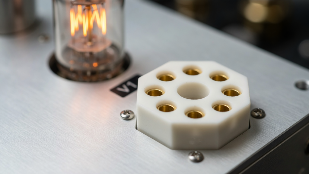
| Chassis Audio | Steatite Ceramic / Teflon | Solder Tabs | Tube Amps & High-Voltage Gear | Superior heat dissipation and high-voltage insulation |
| PCB Integration | Polyphenylene Sulfide (PPS) | PCB Pins | Production Audio & Power Modules | Compact footprint and clean solder joints |
Specifically, pay close attention to contact metallurgy when choosing your upgrade. If your equipment operates under continuous heat, phosphor bronze or beryllium copper contacts ensure tight grip tension over repeated insertions. Alternatively, if your design uses a printed circuit board, a specialized PCB mount octal socket keeps the profile low and prevents trace lifting during maintenance. By matching these material specs to your exact system demands, you eliminate common failure points before the gear ever leaves your bench.
Industrial Relay Sockets: DIN Rail and Panel Mounts
At the same time, upgrading to a premium relay socket with heavy-duty screw terminals directly resolves the connection degradation common in older control panels. When diagnosing unstable system logic, swapping worn bases for a rugged DIN rail mount socket quickly restores circuit integrity.
To select the correct upgrade, evaluate your specific operational conditions:
-
High-Vibration Environments: If you are servicing machinery cabinets that experience continuous movement, a DIN rail mount base with pressure-plate screw terminals prevents stranded copper wires from fraying or backing out over time.
-
High-Temperature Industrial Areas: If your cabinet houses power-dense control circuits, upgrading to a ceramic socket ensures the housing will not warp or carbon-track under elevated thermal loads.
-
Chassis-to-Board Transitions: If you are retrofitting older controls that utilize direct soldering, transitioning to a dedicated PCB mount socket with heavy copper alloy pins protects delicate board traces from heat damage during future maintenance.
-
Legacy Integration: If your bench repairs involve specialized hybrid industrial equipment using a legacy vacuum tube socket, using a chassis-mount octal base with reinforced metal retaining clips keeps the component physically locked in place.
During installation, pay close attention to the terminal clamping mechanism. Avoid cheap, leaf-spring style terminals that pinch only a few wire strands. Instead, choose heavy-duty pressure clamps that distribute screw torque evenly across the entire wire end. This mechanical design guarantees low contact resistance and keeps your industrial system running reliably on the factory floor.
Audiophile Vacuum Tube Sockets: Ceramic and Teflon Options
When applying this focus on physical reliability to tube-driven gear, the choice of vacuum tube socket material dictates your long-term performance.
-
High-Heat Power Stages: If your equipment runs high-bias power tubes, then choosing a ceramic socket prevents heat-related structural failure. As a result of their high thermal thresholds, ceramic bases easily withstand the continuous heat radiated by large glass envelopes.
-
Low-Noise Preamplifiers: If you must minimize microphonic interference, then a Teflon socket is superior because it dampens chassis vibrations.
| Material Property | Ceramic Sockets | Teflon (PTFE) Sockets |
|---|---|---|
| Maximum Operating Temp | 500°C+ | 260°C |
| Dielectric Strength | Very High | Excellent |
| Mechanical Characteristics | Rigid, brittle under impact | Soft, absorbs vibration |
| Typical Connection Type | Chassis mount or solder tabs | Solder tabs or PCB mount |
Because of these distinct material profiles, you must match the socket to your specific thermal and mechanical load. For instance, ceramic handles extreme temperatures without warping, but it can crack if you apply uneven force during tube extraction. On the other hand, Teflon offers high moisture resistance and mechanical flexibility, which protects delicate PCB mount connections from structural fatigue. If you are retrofitting older gear on the bench, verify that the physical socket footprint aligns with your chassis spacing before soldering.
Technical Specifications and Material Selection Guide
Once you confirm that physical alignment, upgrading to a premium 8 pin octal socket requires evaluating contact retention. Consequently, cheap sockets lose tension over time, which leads to arcing and localized thermal runaway.
- If vibration causes intermittent signal loss, then install a heavy-duty ceramic socket with wrap-around contacts.
For example, these contacts grip the pins of your vacuum tube socket or relay base far more securely. For this reason, bench technicians must inspect contact material during any standard preventive overhaul.
- If you run high-current industrial panels, then switch to a DIN rail mount relay socket.
Specifically, choose a model that features heavy pressure-plate screw terminals. As a result of this design, your field wiring remains secure without the risk of wire shearing or fatigue.
- If trace lifting occurs on your control boards, then install a dedicated PCB mount socket.
This upgrade protects delicate copper traces from repeated thermal stress during field servicing.
Terminal Construction: Pressure Clamps vs. Solder Tabs
Evaluating terminal construction is the next critical step once you secure the board interface. If you are wiring a chassis-mount vacuum tube socket, then choose hot-solder tabs with mechanical wrap connections. This structural wrap prevents mechanical stress on the solder joint itself. Consequently, the joint remains electrically stable even during intense thermal cycling.
If you deploy a DIN rail mount relay socket in high-vibration areas, then use pressure-plate screw terminals. These clamps compress stranded wire without shearing the delicate copper elements. For this reason, bench technicians can rapidly swap components during preventive maintenance without degrading the physical wire.
| Parameter | Pressure Clamps (Screw Terminals) | Solder Tabs |
|---|---|---|
| Primary Application | Industrial relay socket installations | Chassis-mount vacuum tube socket builds |
| Termination Method | Screw tension on pressure plate | Hand soldering with mechanical wrap |
| Max Current Rating | Up to 15A continuous | Up to 10A continuous |
| Vibration Resistance | High (retains torque under load) | Moderate (joints prone to crystallization) |
| Field Serviceability | Excellent (requires only a screwdriver) | Poor (requires a hot soldering iron) |
If your system demands frequent component changes under tight deadlines, then pressure clamps are the superior operational choice. Conversely, if your circuit requires minimal contact resistance in a high-temperature chassis, then choose high-purity brass solder tabs.
Structural Integrity: One-Piece Stamped Metal vs. Welded Interconnects
Evaluating the physical construction of these tabs and terminal pins reveals a critical division in how the internal socket contacts are manufactured. If you install a low-cost octal relay socket or vacuum tube socket, then you will likely encounter either one-piece stamped metal contacts or multi-piece welded interconnects.
As a rule, one-piece stamped contacts are punched and formed from a single sheet of spring-temper alloy, such as phosphor bronze, Because there are no metallurgical joints, these contacts maintain consistent mechanical tension against the component pins over thousands of insertion cycles. If your application involves continuous thermal cycling, then you must select one-piece stamped contacts to eliminate the risk of joint separation.
Conversely, welded interconnects join a separate contact basket to a terminal pin using spot welding. Consequently, these welds act as stress-concentration points. If a heavy-duty ceramic socket with welded pins is subjected to mechanical vibration, then the weld joints can fracture and cause an open circuit.
| Structural Metric | One-Piece Stamped Metal | Welded Interconnects |
|---|---|---|
| Failure Points | None (monolithic construction) | High (spot-weld interface) |
| Spring Retention | Excellent long-term fatigue limit | Variable; affected by weld heat |
| Contact Resistance | Low and uniform (< 5 mΩ) | Higher at the weld joint over time |
| Common Applications | High-reliability PCB mount & chassis sockets | Budget-grade industrial relay socket designs |
If you are sourcing components for a critical PCB mount system, then prioritize one-piece stamped beryllium copper. This alloy offers the highest fatigue strength under load. Ultimately, avoiding welded joints prevents localized resistance increases that lead to catastrophic socket failure.
Comparing Leading 8 Pin Octal Socket Models
To implement these rugged, one-piece contact designs in your actual hardware upgrades, you must evaluate the leading 8-pin octal sockets based on their mounting style and insulation material. Selecting the wrong model introduces immediate mechanical bottlenecks into your signal or power paths. Consequently, your choice depends entirely on whether you are servicing an industrial control panel or rebuilding a high-voltage vacuum tube amplifier.
If your application requires rapid deployment on a standard rail, then you must select an industrial relay socket with integrated screw terminals. Specifically, the Omron PF083A-E serves as the benchmark for industrial control circuits. This model utilizes a rugged DIN rail mount housing to simplify cabinet layouts. As a result, it secures wire runs safely away from moving parts. In contrast, if your system operates at high temperatures, then a chassis-mount ceramic socket is mandatory. Premium ceramic designs utilize one-piece phosphor bronze contacts wrapped in a glazed steatite ceramic body. This configuration prevents structural deformation when exposed to the intense thermal radiation of power tubes.
If you are designing high-performance audio or RF equipment, then a Teflon PCB mount socket is the optimal upgrade path. Teflon offers an exceptionally low dielectric constant, which minimizes high-frequency signal loss. For this reason, upgrading from standard phenolic sockets to Teflon or ceramic variants directly improves signal integrity.
| Socket Model / Type | Typical Mount | Primary Material | Contact Design | Target Application |
|---|---|---|---|---|
| Omron PF083A-E | DIN Rail / Surface | Flame-Retardant Plastic | Screw Terminals (Pressure Clamp) | Industrial relay socket & automation |
| Belton 8-Pin Octal | Chassis Mount | Glass-Filled PPS | One-Piece Phosphor Bronze | Vacuum tube socket for amplifiers |
| Premium Ceramic Octal | Chassis Mount | Glazed Steatite Ceramic | One-Piece Silver-Plated Copper | High-temp vacuum tube socket (KT88/EL34) |
| Teflon 8-Pin PCB | PCB Mount | Virgin PTFE (Teflon) | One-Piece Gold-Plated Beryllium | High-frequency RF & premium audiophile |
If you install a chassis-mount socket in a high-vibration environment, then you must secure it with spring-steel retaining clips. This step prevents the component from backing out of its housing over time. Ultimately, matching the mechanical mounting style to your specific operating environment prevents premature contact wear and field failures.
Installation and Wiring Best Practices for Octal Sockets
To execute a successful system upgrade, you must first evaluate your socket’s current electrical and thermal profile. Specifically, if you are upgrading an industrial control cabinet, then you must select a heavy-duty DIN rail mount relay socket. This configuration uses secure screw terminals to ensure positive pressure on conductors and prevent vibration-induced faults.
If your upgrade target is a high-temperature environment, then you must transition from standard phenolic variants to a glazed ceramic socket. Standard phenolic materials degrade under high thermal loads. In contrast, ceramic bodies isolate high voltages safely and maintain their mechanical dimensions up to 250°C.
For this reason, if your circuit design requires direct board integration, then you must deploy a dedicated PCB mount vacuum tube socket containing one-piece contacts. Selecting one-piece alloy contacts prevents the metallurgical joint fractures common to multi-piece welded pins. As a direct result, targeted upgrades optimize terminal conductivity and prevent costly system downtime in critical hardware.
DIN Rail Mounting and Chassis Integration
If you are executing a system-wide upgrade of legacy hardware, then you must systematically verify both the physical mounting footprint and the electrical load characteristics of your replacement components. Specifically, selecting the incorrect socket profile during a retrofitting phase will result in physical alignment issues or catastrophic insulation breakdown.
To assist in this selection process, the table below outlines the core specifications for the three primary octal socket configurations used in modern industrial and audio systems.
| Socket Type | Mounting Configuration | Primary Material | Termination Style | Max Temperature | Optimal Application |
|---|---|---|---|---|---|
| Industrial Relay Socket | DIN rail mount or surface panel | Reinforced Phenolic / Nylon | Screw terminals with pressure plates | 85°C to 125°C | Industrial automation, control relays, timers |
| High-Performance Ceramic Socket | Chassis mount with retaining clip | Glazed Steatite Ceramic | Solder tabs or wrap posts | 250°C | Power amplifier vacuum tube socket, RF gear |
| Direct PCB Mount Socket | PCB mount (through-board) | Glass-filled Polyester | Solid one-piece alloy pins | 105°C | Printed circuit board integration, pre-amps |
if your upgrade involves high-current industrial control relays, then you must install a heavy-duty DIN rail mount relay socket featuring pressure-plate screw terminals. This design secures the stranded wire without severing individual copper filaments. Conversely, if you are servicing high-voltage audiophile equipment, then you must replace degraded sockets with a chassis-mount ceramic socket. The glazed ceramic construction prevents arc-over between adjacent pins, which is a common failure mode in older, carbon-tracked phenolic bases. Finally, if your project utilizes a PCB mount layout, then you must align the replacement pin circle precisely with the board pads to prevent mechanical stress on the solder joints.
Wire Gauge and Torque Requirements for AWG 12
Aligning the pin circle precisely prevents localized physical stress, but managing the heavy mechanical load of thick-gauge conductors requires equal precision. If you are routing AWG 12 solid or stranded conductors to a heavy-duty DIN rail mount relay socket, then you must torque the screw terminals to exactly 0.8 Nm (7.1 in-lbs) to avoid damaging the threads or leaving the joint under-tightened, Because AWG 12 wire exerts significant torsional force, failing to secure the wire properly leads to contact separation and localized overheating.
To guarantee high conductivity, you must match the terminal hardware to the wire type. Specifically, if you use stranded AWG 12 wire, then you must select a relay socket with pressure-plate screw terminals rather than direct-acting screws. Direct-acting screws shear individual copper strands during tightening, which dramatically reduces the effective cross-sectional area. Consequently, this localized neckdown increases terminal resistance and can cause thermal runaway under peak current loads.
| Socket Type | Terminal Interface | Wire Gauge Capacity | Target Torque Rating | Terminal Contact Material |
|---|---|---|---|---|
| Heavy-Duty DIN Rail Mount | Pressure-plate screw terminals | AWG 12 to AWG 20 | 0.8 Nm (7.1 in-lbs) | Nickel-plated brass |
| Standard Relay Socket | Direct-screw clamp | AWG 14 to AWG 22 | 0.5 Nm (4.4 in-lbs) | Tin-plated steel |
| Chassis Mount Ceramic Socket | Solder tabs (turret/wrap) | AWG 12 Max (Solder) | N/A (Solder joint) | Silver-plated phosphor bronze |
As a result of these physical constraints, when upgrading high-power industrial systems or vintage vacuum tube socket connections, the installer must verify the mechanical limits of the socket chassis. If you exceed the maximum torque specification of the mounting screws on a ceramic socket, then you will fracture the brittle steatite body. To prevent this failure mode, you must use torque-limiting drivers during the final installation phase.
FAQ About 8 pin octal sockets
Can industrial 8 pin octal sockets be used for vacuum tubes?
you must apply this mechanical caution when evaluating whether an industrial relay socket can function as a vacuum tube socket. If you install a standard relay socket in a tube amplifier, then you must verify the housing temperature limits.
Specifically, industrial DIN rail mount sockets typically use glass-filled nylon or PBT plastics. These polymers degrade rapidly when exposed to the sustained 150°C to 250°C operating temperatures of power tubes. If you require sustained high-temperature operation, then you must deploy a ceramic socket or a Teflon-based socket instead.
Also, electrical spacing is a critical safety factor. Industrial screw terminals are rated for control-level voltages. If your plate voltage exceeds 300V DC, then you must reject standard relay sockets to avoid dielectric breakdown and destructive arcing between adjacent pins.
| Parameter | Industrial DIN Rail Relay Socket | Dedicated Ceramic Vacuum Tube Socket |
|---|---|---|
| Base Material | Glass-filled nylon / PBT | Steatite ceramic |
| Max Temperature | 85°C to 105°C | 250°C+ |
| Voltage Rating | 300V to 600V AC | 1000V+ DC |
| Connection Style | Screw terminals | Solder tabs / PCB mount |
If you require a low-loss RF or audio connection, then you must select a PCB mount ceramic socket with silver-plated contacts. Therefore, industrial sockets are only acceptable for low-temperature preamplifier tubes operating at low voltages.
What is the maximum wire gauge supported by standard octal relay sockets?
If you exceed these low-voltage limits, then you must upgrade to a heavy-duty DIN rail mount socket. This upgrade must accommodate thicker conductors safely. Standard relay socket terminals are typically rated for a maximum wire gauge of AWG 14. However, if you run high-current industrial control loops or high-power heater filaments, then you must select an upgraded socket designed specifically for AWG 12 wiring.
If you use standard AWG 12 wire in a conventional socket, then you will exceed the physical physical limit of the terminal slots. This mismatch forces field technicians to trim wire strands to fit the terminal. If you reduce the conductor cross-sectional area by shearing strands, then you create a localized high-resistance point. This electrical bottleneck leads directly to thermal runaway under continuous load.
To safely execute a heavy-duty upgrade, evaluate the mechanical terminal interface using the specifications below:
| Upgrade Parameter | Standard Relay Socket | Heavy-Duty Upgraded Socket |
|---|---|---|
| Max Wire Gauge | AWG 14 (Solid/Stranded) | AWG 12 (Stranded with ferrule) |
| Terminal Connection | Direct-acting screw | Pressure-plate clamp |
| Max Torque Rating | 0.5 Nm (4.4 in-lbs) | 0.8 Nm (7.1 in-lbs) |
| Terminal Material | Brass / Zinc-plated steel | Nickel-plated copper alloy |
If your application demands AWG 12 conductors, then you must verify that the socket features pressure-plate screw terminals. Standard direct-acting screws tear individual copper strands during tightening. Additionally, if you use a ceramic socket for high-temperature vacuum tube applications, then you must also use a torque-limiting driver set to exactly 0.8 Nm (7.1 in-lbs). Exceeding this torque limit will fracture the brittle steatite body, rendering the installation useless and hazardous.
How do ceramic octal sockets compare to Teflon sockets in thermal performance?
If you upgrade a standard relay socket to a high-temperature vacuum tube socket, then you must evaluate how ceramic and Teflon materials behave under extreme thermal loads. Unlike a standard industrial DIN rail mount socket designed for cool-running control relays, an active vacuum tube socket must continuously dissipate intense radiant heat. Consequently, selecting the wrong socket material leads directly to structural deformation or catastrophic dielectric breakdown.
| Material Property | Steatite Ceramic Socket | Teflon (PTFE) Socket |
|---|---|---|
| Max Continuous Temp | 1000°C (1832°F) | 250°C (482°F) |
| Thermal Shock Resistance | Moderate (Prone to cracking) | High (Deforms but does not crack) |
| Dielectric Loss Factor | Low (0.0020 at 1 MHz) | Ultra-Low (0.0001 at 1 MHz) |
| Physical Durability | Brittle (Vulnerable to over-torque) | Malleable (Resistant to impact) |
| Outgassing Risk | Zero | High (Releases toxic HF gas above 260°C) |
If your application subjects the socket to temperatures exceeding 250°C, then you must specify a ceramic socket to prevent terminal misalignment. Specifically, high-power output tubes generate rapid thermal cycles that melt softer fluoropolymers. If you choose a ceramic socket for a PCB mount configuration, then you must also provide mechanical strain relief for the solder joints. Ceramic does not flex, which transfers all thermal expansion stress directly to the PCB copper traces.
In contrast, if your circuit operates in a high-vibration environment under 200°C, then you should select a Teflon socket to prevent mechanical fractures. Teflon absorbs physical shocks that would instantly shatter a brittle ceramic socket. However, if you use a Teflon socket with screw terminals, then you must verify terminal tightness after the first thermal cycle, Because Teflon exhibits cold-flow characteristics under pressure, the material will slowly deform under the clamp load, which reduces terminal torque and increases contact resistance over time.