Selecting the right capacitor determines whether your high-frequency system succeeds or fails. Metallized polypropylene (MPP) capacitors offer the precise balance of low dielectric loss and high insulation resistance needed for demanding hardware.
At the core of these components is a thin polypropylene film dielectric. This material is coated with a micro-thin, vacuum-deposited metallized film layer, Because of this construction, the capacitor possesses a critical self-healing property. If a localized dielectric breakdown occurs under voltage stress, rapid vaporization clears the fault area. This process prevents catastrophic short circuits and preserves nominal capacitance over years of operation.
To put this in perspective, choosing between major manufacturers like WIMA, KEMET, Vishay, and TDK Electronics (EPCOS) requires looking far beyond basic datasheets. You must balance equivalent series resistance (ESR) against thermal limits and long-term drift. This engineering guide delivers the raw performance data and brand comparisons you need. Use these trade-offs to select the optimal component for your next industrial, automotive, or high-end audio project.
Understanding Metallized Polypropylene Capacitors: Construction and Physics
Achieving this level of optimization requires you to analyze the physical interface between the polypropylene film and the vacuum-deposited metal electrodes. Specifically, the electrical performance of any film capacitor depends on the molecular structure of its dielectric. Polypropylene is a semi-crystalline polymer. Consequently, it exhibits an exceptionally symmetric molecular structure that minimizes dipolar polarization losses under alternating electric fields.
In practice, this molecular symmetry delivers a lower dissipation factor than other polymer dielectrics. When you select a metallized film over a traditional discrete foil, you substitute thick metal sheets with a micro-thin layer of aluminum or zinc. This metallic layer is vacuum-deposited directly onto the polymer surface. To help you evaluate these materials, the table below contrasts the raw physical limits of polypropylene against alternative polymer films.
| Dielectric Material | Dielectric Constant (εr at 1 kHz) | Dissipation Factor (tanδ at 1 kHz) | Dielectric Strength (V/µm) | Max Operating Temp (°C) |
|---|---|---|---|---|
| Polypropylene (PP) | 2.2 | 0.0002 | 650 | 105 |
| Polyester (PET) | 3.3 | 0.0050 | 400 | 125 |
| Polycarbonate (PC) | 3.0 | 0.0015 | 450 | 125 |
Because the metallized electrodes are incredibly thin—typically measuring between 20 and 50 nanometers—the film capacitor gains its self-healing capability. Consequently, a localized electrical breakdown vaporizes the thin metal around the fault spot instead of creating a permanent short circuit. However, you must design around the fact that these thin electrodes increase the equivalent series resistance compared to heavy-foil designs. Ultimately, mastering these basic physical trade-offs prevents field failures in high-frequency and high-voltage power paths.
Critical Technical Specifications and Performance Limits
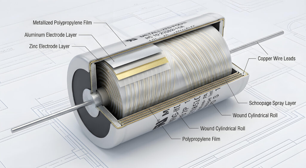
To master these power paths in modern hardware, you must understand exactly how a metallized polypropylene capacitor is assembled. Unlike traditional designs that use thick, separate foil sheets, this specific film capacitor utilizes an ultra-thin metallized film. This unique configuration, found in industry-standard series like the WIMA MKP 4 or KEMET R46 series (e.g., R46KI310000M1M), serves as both the dielectric and the conducting electrodes. Manufacturers vapor-deposit a zinc or aluminum layer directly onto the underlying polypropylene film to minimize overall component volume.
These metallized sheets are then wound into a tight cylinder or stacked in layers to reach the target capacitance. To connect these internal layers to the external terminals, manufacturers spray molten metal onto the ends of the wound roll. This end-contact process, known as schoopage, is critical because it determines how well the unit handles peak currents.
As a direct consequence of this architecture, the thin metallization enables a self-healing action during localized voltage breakdowns. However, you must design around the fact that these thin electrodes increase the equivalent series resistance compared to heavy-foil designs. Therefore, you must balance the benefits of a self-healing dielectric against your system’s overall thermal dissipation limits. When choosing between wound or stacked variations, remember that wound types offer better voltage handling, while stacked types provide superior volumetric efficiency. Your choice directly impacts the overall reliability of your power stage.
Primary Applications in Modern Engineering and Audio
To guarantee this reliability under transient overvoltages, you must understand the physics of the self-healing mechanism within the polypropylene film dielectric. This process is highly optimized in safety-rated components like the KEMET F862 metallized polypropylene series. When a localized defect or impurity experiences electrical breakdown, a micro-arc forms at the failure point. This arc rapidly heats the localized area to temperatures between 3,000°C and 6,000°C. Consequently, the ultra-thin metallized electrodes vaporize immediately around the fault.
The resulting plasma pressure blows the vaporized metal outward, leaving a clear, non-conductive margin around the puncture, Because of this rapid process, the short circuit is isolated within microseconds, and the film capacitor recovers its insulation resistance. Your system continues to operate without immediate downtime.
       Overvoltage Spike -> Localized Dielectric Breakdown
                                 │
                                 ▼
                     Formation of Micro-Arc (Plasma)
                                 │
                                 ▼
               Vaporization of Thin Metallized Layer
                                 │
                                 ▼
           Arc Extinguished -> Non-Conductive Margin Formed
                                 │
                                 ▼
               Insulation Resistance Restored (< 10 µs)
As a designer, you must not treat this clearing action as an infinite safety net. Specifically, each clearing event burns away a tiny fraction of the active electrode, which causes an incremental drop in overall capacitance. If your circuit subjects the component to continuous overvoltage or excessive ripple current, repeated clearing events will build internal gas pressure.
To prevent catastrophic housing rupture or thermal runaway, you must select your capacitor series based on the physical limits of the clearing process.
| Parameter | Typical Value / Range | Impact on Design |
|---|---|---|
| Clearing Energy (Ec) | 10-6 to 10-5 Joules | Determines the minimum energy required to clear a fault safely. |
| Arc Temperature | 3,000°C to 6,000°C | Requires high-grade polymer to prevent carbonization during clearing. |
| Clearing Time | 1 to 10 µs | Rapid isolation prevents grid-level protection or fuses from tripping. |
| Electrode Thickness | 10 to 50 nm | Thinner layers clear more reliably but increase equivalent series resistance (ESR). |
If you operate the capacitor below its minimum clearing energy, the arc will not contain enough energy to vaporize the metal completely. Consequently, the short circuit will remain active, leading to localized heating and eventual component destruction. Conversely, exceeding the maximum energy limits will melt the underlying polypropylene film, leading to a permanent short circuit. You must balance your system’s transient energy profiles against these physical boundaries to ensure long-term reliability in the field.
Selecting Metallized Polypropylene Capacitors: Brand and Series Comparison
To balance these energy boundaries while meeting tight board space constraints, you must master the trade-offs of volumetric efficiency between metallized film and traditional foil designs. Your choice directly impacts the physical footprint and thermal management of your power stage, Because the electrodes in a metallized film capacitor are vapor-deposited directly onto the polypropylene film dielectric at nanometer-scale thickness, the resulting component is incredibly compact. In contrast, traditional foil-and-film capacitors employ separate, discrete sheets of metal foil as electrodes. Consequently, these metal foils add significant inactive volume to the winding.
By eliminating this physical metal layer, a metallized film design like the WIMA MKP 10 delivers a massive boost in capacitance per unit volume. As a result, you can shrink your PCB footprint significantly. However, you must recognize that this volumetric efficiency comes with severe electrical compromises.
| Parameter | Metallized Polypropylene Film | Traditional Foil-and-Film | Design Impact |
|---|---|---|---|
| Electrode Thickness | 10 to 50 nm | 5 to 6 µm | Thin layers maximize active dielectric area within the package. |
| Volumetric Efficiency | High (Up to 1.5 µF/cm3) | Low (Typically < 0.3 µF/cm3) | Directly dictates your total PCB space requirements. |
| Self-Healing Ability | Active | Non-existent | Foil types fail short-circuit; metallized types isolate faults. |
| Peak Current (Ipeak / dV/dt) | Moderate | Exceptionally High | Foil types survive high-energy pulses without degradation. |
Because of the thinness of the vapor-deposited electrodes, metallized variations exhibit much higher equivalent series resistance (ESR). For this reason, you cannot expect a highly compact metallized capacitor to handle the same peak pulse currents as a bulky, traditional foil-and-film capacitor like the WIMA FKP 1 series. If your application involves extreme dV/dt transients, such as heavy-duty snubber circuits, you must select traditional foil designs despite their footprint penalty.
To prevent field failures, you must calculate your exact peak current requirements before prioritizing a smaller enclosure. Do not compromise the thermal stability of your system simply to achieve a more compact layout.
Disadvantages, Limitations, and Failure Modes
Designing for thermal stability requires you to master the core electrical limits of the polypropylene film dielectric under high AC stress. You cannot treat these components as ideal capacitors in your simulations.
FAQ About metallized polypropylene capacitors
Voltage Ratings, Ripple Current, and dV/dt Slew Rates
Once you establish the true ESR at your operating frequency, you must immediately confront the dual challenge of voltage ratings and dV/dt limits. You cannot assume that a DC voltage rating applies to AC or pulsed waveforms. Under high-frequency AC operation, the voltage limit of a polypropylene film capacitor is not bounded by the dielectric breakdown of the film, but rather by the onset of corona discharge and internal heating.
You must drastically derate the operational voltage when your circuit subjects the film capacitor to continuous AC ripple. For instance, a part rated for 630 VDC might only tolerate 250 VAC at 50/60 Hz; this limit drops further as the frequency rises into the kilohertz range.
To visualize this limitation, study the relationship between DC voltage, AC voltage, and the maximum allowable dV/dt slew rate across typical metallized film ratings:
| Rated DC Voltage (VDC) | Max Continuous AC Voltage (VRMS at 60Hz) | Typical dV/dt Slew Rate Limit (V/µs) | Maximum Peak Current Limit (Ipk) |
|---|---|---|---|
| 250 VDC | 160 VAC | 15 to 30 | C×(dVdt) |
| 400 VDC | 220 VAC | 20 to 50 | C×(dVdt) |
| 630 VDC | 250 VAC | 30 to 90 | C×(dVdt) |
| 1000 VDC | 350 VAC | 100 to 250 | C×(dVdt) |
For high-pulse applications, selecting a specialized series such as the TDK Electronics B32652 series (e.g., B32652A6104K000, 0.1 µF, 630 VDC) provides the construction necessary to handle dV/dt ratings of up to 400 V/µs.
In addition to absolute voltage limits, you must calculate the peak current generated by fast switching edges. The maximum dV/dt rating defines the physical capability of the junction between the zinc end-spray and the thin electrodes. When you subject the capacitor to a rapid voltage change, the peak current flows entirely through this thin contact zone.
If your circuit exceeds the rated dV/dt, the high current density will burn away the contact layer. As a direct result, the capacitor will suffer a massive, permanent loss of capacitance because sections of the dielectric become electrically isolated from the terminals.
Also, this localized degradation bypasses the standard self-healing mechanism. Instead of clearing a localized point defect, the overstressed contact area degrades progressively, leading to open-circuit failures or catastrophic thermal destruction. For this reason, you must always measure the fastest switching transitions in your actual prototype. Do not rely on nominal simulations; verify that your worst-case dV/dt remains safely below the manufacturer datasheet limit.
Thermal Performance and Temperature Derating Curves
Once you verify those actual physical switching speeds, you must immediately translate those electrical metrics into thermal losses. This step is vital because internal heat is the ultimate limiting factor for any metallized film capacitor. Specifically, polypropylene film exhibits a strict thermal limit that you cannot compromise, While it possesses outstanding dielectric properties at room temperature, its physical strength degrades rapidly above 85°C.
You must apply rigorous voltage derating when operating in hot environments. For example, the Vishay MKP1848 DC-Link series supports 100% of its rated voltage up to 85°C but must be derated linearly to 70% of its rated voltage when operating at 105°C. If you exceed these thermal limits, the dielectric weakens, which triggers frequent self-healing clearing events, Because each clearing event vaporizes a small portion of the metallized electrodes, your circuit will experience a progressive loss of capacitance. To prevent this failure, you