
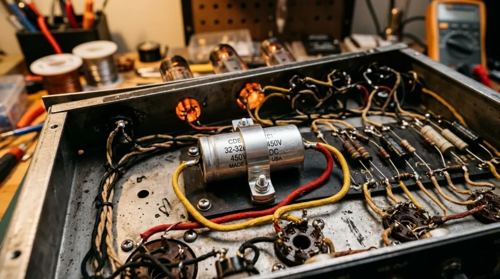
More importantly, replacing a 32uF capacitor with a 525V rating is critical when servicing high-voltage hardware. This is especially true for vintage tube amplifier restorations and specialized lighting ballasts. At these high voltages, cheap components fail quickly under thermal and ripple stress.
As a bench technician, I know that mechanical fit is just as important as electrical specs. For instance, you must choose between a traditional chassis-mount can capacitor and a compact radial capacitor. Circuit board space often dictates this layout choice. A classic metal-can design will also require a matching mounting clamp for a secure, grounded fit.
In practice, this technical review evaluates the top 525V electrolytic capacitor options available for purchase right now. We compare physical dimensions, lead spacing, and thermal ratings. This data ensures you find the exact replacement to keep your high-value equipment running safely.
Understanding the Key Applications of a 32uF Capacitor
At the same time, to get the best performance from your high-voltage gear, you must look closely at the mechanical and electrical specifications of the replacement parts currently on the market. For classic tube amplifier restoration, the F&T 32uF + 32uF 500V/550V surge dual-section can capacitor is a standard bench choice. This electrolytic capacitor packages two independent filter sections into a single compact housing. It measures 35mm in diameter and 50mm in height, Because of this specific footprint, you will need a matching 35mm (1-3/8 inch) metal mounting clamp to secure it safely to the amplifier chassis. The solder lugs on the bottom allow for clean, vintage-style point-to-point hand wiring.
If your layout uses a circuit board instead of chassis-mounted wiring, space constraints will point you toward a single-ended radial capacitor or an axial capacitor design. High-quality radial options from specialty manufacturers offer a significantly smaller footprint on the board. They feature tight lead spacing, typically 7.5mm or 10mm, which matches vintage PCB grid configurations. When replacing a horizontal axial capacitor, pay close attention to the overall length of the component body. A modern 32uF 525V axial unit is often narrower but longer than its vintage counterpart. This difference in length requires you to carefully pre-bend the leads to avoid putting physical stress on the end seals during installation.
For industrial lighting and heavy-duty AC machinery, you must switch from polarized DC designs to a non-polarized oil filled AC ballast capacitor. These heavy-duty components are specifically built for high continuous AC currents. They typically feature a rugged, hermetically sealed aluminum case with quick-connect spade terminals on top. Unlike an electrolytic capacitor, these oil-filled units are built to run cool under extreme ripple currents. They also measure significantly larger than DC-rated capacitors of the same nominal capacitance. Consequently, you must verify the mounting bracket clearance inside your ballast enclosure before purchasing a replacement.
High-Intensity Discharge and 1500W Metal Halide Lighting Systems
Because of these tight physical spacing constraints in commercial enclosures, selecting a replacement 32uF 525V capacitor for a 1500W metal halide ballast requires a careful balance of physical size and electrical durability. For this reason, standard DC filter designs, such as a polarized electrolytic capacitor or a multi-section can capacitor, are completely unsuitable here. Those components are designed specifically for direct-current filtering in a tube amplifier or a low-frequency power supply. Instead, high-intensity discharge (HID) lighting systems subject the capacitor to continuous, high-amplitude alternating current.
To ensure long-term reliability on your service bench, you must evaluate several critical mechanical and electrical specifications:
-
Voltage and AC Rating: Ensure the replacement is explicitly rated for 525VAC continuous operation rather than DC peak voltage. Using a standard DC-rated radial capacitor or axial capacitor in this high-voltage AC circuit will cause immediate dielectric breakdown and catastrophic component failure.
-
Physical Case Footprint: These heavy-duty components are typically housed in oval or cylindrical aluminum enclosures. Before ordering, verify the height and base dimensions of the chassis area to ensure the unit fits safely within the existing ballast tray.
-
Mounting and Vibration Control: Because ballast transformers hum and vibrate constantly during operation, you must secure the new capacitor using a heavy-duty steel mounting clamp. A loose capacitor will eventually suffer from fatigued solder joints or broken quick-connect spade terminals.
-
Thermal and Safety Ratings: Always select a dry or oil filled capacitor with a minimum temperature rating of 85°C, though a 105°C rating is highly preferred for enclosed commercial fixtures. Additionally, the capacitor must feature an internal pressure-sensitive interrupter to safely disconnect the circuit if internal pressure builds.
Vintage Tube Amplifiers and Classic Audio Gear
While industrial ballasts demand these rugged AC safety features, servicing a classic tube amplifier requires a different but equally strict set of high-voltage DC parameters. Modern mains voltages often run higher than the vintage design specs of the mid-twentieth century. Consequently, a 32uF electrolytic capacitor rated for 500VDC or 525VDC is now the mandatory benchmark for the primary filter stage.
For example, during startup, before the vacuum tubes warm up and begin drawing current, the power supply voltage surges to its peak unloaded value. If you install an underrated component here, the surge will easily exceed its maximum rating and puncture the dielectric. For this reason, always select a high-grade aluminum can capacitor with a surge rating of at least 550VDC to handle these transient spikes safely.
When sourcing your replacement, physical chassis layout dictates the form factor. Specifically, you can choose a traditional twist-lock multi-section can or mount individual modern components beneath the chassis. If you choose the under-chassis route, you must secure a high-voltage axial capacitor or radial capacitor using silicone adhesive or a dedicated terminal strip. Loose components in a high-voltage audio circuit will cause mechanical vibration and premature lead failure.
Conversely, when replacing a chassis-mounted can, you must install a heavy-duty metal mounting clamp to ground the shell securely to the chassis. Maintaining a low-resistance ground path prevents ground loops and eliminates unwanted hum in the audio signal. For specialized high-end audiophile gear, some technicians even opt for a sealed oil filled paper capacitor to achieve maximum reliability, provided the chassis has enough physical space.
Technical Specifications for High-Voltage 32uF Capacitors
Evaluating these spatial tradeoffs brings us directly to the critical electrical limits of your replacement component. When servicing high-stress circuits, you must verify that the replacement 32uF capacitor is rated for a continuous 525V load. This rating prevents internal arcing and premature dielectric failure. In standard applications, a generic electrolytic capacitor rated for only 450V will degrade rapidly under transient voltage spikes.
For industrial lighting gear, you must source an oil filled AC capacitor specifically designed for continuous 525VAC service. Do not use a DC-rated can capacitor in these AC ballast environments. Doing so guarantees immediate dielectric breakdown. Conversely, for a vintage tube amplifier, you must focus on DC working voltage and peak surge ratings. A premium 525VDC radial capacitor or axial capacitor provides the crucial voltage headroom during cold power-on cycles.
When purchasing your replacement components, verify these exact technical parameters on the manufacturer’s datasheet:
-
Voltage Margin: Confirm a minimum 525V working rating (AC for ballasts, DC for amplifiers).
-
Physical Mounting: Ensure the outer diameter matches your existing metal mounting clamp to guarantee mechanical stability.
-
Temperature Tolerance: Select components rated for at least 85°C, though 105°C is highly recommended for enclosed, high-heat chassis environments.
-
Safety Interrupter: For AC ballast replacements, check for an internal pressure-sensitive switch to prevent housing rupture.
Matching these exact specifications protects delicate circuitry and ensures long-term bench reliability.
Voltage Ratings and Operating Safety Margins (500V vs. 525V)
To achieve this bench reliability, you must evaluate the critical differences between 500V and 525V ratings when sourcing a replacement 32uF capacitor.
In a vintage tube amplifier, startup voltages frequently spike well above the nominal operating level. This surge occurs because the rectifier delivers full voltage before the power tubes heat up and draw current. As a result, a standard 500V electrolytic capacitor will operate dangerously close to its dielectric limit during these cold-start cycles. To prevent immediate insulation breakdown, you must step up to a 525V rating. This extra 25V margin provides the vital safety headroom needed to absorb these transient turn-on surges without degrading the component’s service life.
When planning your physical installation, check your mounting configuration carefully. For instance, a heavy-duty 525V can capacitor often demands a precise metal mounting clamp to secure its chassis footprint. On the other hand, point-to-point vintage chassis designs may require a high-voltage radial capacitor or axial capacitor. In these cases, verify that the lead length and spacing match your terminal strips to avoid mechanical stress on the solder joints.
Finally, remember that industrial lighting ballasts require a specialized oil filled AC-rated capacitor. Never substitute a DC-rated electrolytic component in these demanding high-voltage AC environments, as the continuous AC voltage reversals will cause immediate thermal failure.
Physical Dimensions of Axial and Radial Capacitor Designs
Because DC applications like a vintage tube amplifier demand specific physical layouts, you must map your chassis constraints before purchasing a replacement 32uF 525V electrolytic capacitor. Consequently, choosing between an axial capacitor and a radial capacitor is not merely a preference; it dictates your entire safety and mounting strategy.
To ensure a secure mechanical fit and prevent bench failures, you must adhere to these precise dimensional guidelines:
-
Axial Lead Configurations: A typical 525V axial design measures approximately 20mm in diameter by 45mm in length. You must secure the body of this component directly to terminal strips or use a dedicated physical tie-down. Never allow the capacitor to suspend freely by its leads, as chassis vibration will eventually fracture the solder joints.
-
Radial Lead Configurations: These vertical-mount units generally measure 22mm in diameter by 35mm in height, Because of this compact vertical stance, they save valuable horizontal board space but require adequate overhead clearance. Always confirm your chassis cover provides at least 10mm of clearance above the capacitor tip to prevent high-voltage arcing to the metal enclosure.
-
Can Capacitor Configurations: Twist-lock or clamp-mount can designs usually feature a standard 35mm (1.375-inch) diameter. For this reason, you must verify that your metal mounting clamp matches this exact diameter before installation. Do not attempt to overtighten an oversized clamp or pad an undersized bracket with tape, as this compromises both mechanical stability and thermal dissipation.
Before final soldering, check the physical spacing between high-heat components. You must maintain a minimum 15mm clearance between your 525V capacitor and any power resistors or vacuum tubes. Failure to maintain this gap will cause rapid thermal degradation and lead to catastrophic dielectric breakdown.
Oil-Filled vs. Dry Electrolytic Capacitor Construction
Preventing this thermal breakdown requires understanding how an oil filled capacitor differs from a dry electrolytic capacitor under high-voltage stress. Consequently, you must analyze the dielectric construction before finalizing your purchasing decision.
For a classic tube amplifier, a dry electrolytic capacitor provides the high capacitance-to-volume ratio needed for tight chassis layouts. However, these dry units degrade significantly faster than their oil-filled counterparts when exposed to high ripple currents. In contrast, heavy-duty metal halide ballasts subject the component to continuous AC currents, demanding a robust oil filled design.
Never substitute a dry electrolytic radial capacitor into an AC ballast circuit, as this causes immediate, catastrophic rupture. Furthermore, always secure heavy oil-filled cans with a dedicated mounting clamp bolted directly to the metal frame. By contrast, an axial capacitor or dual can capacitor in audio gear relies on passive ventilation to survive. Do not take shortcuts on voltage tolerances. Always verify that your 525V component handles peak startup surge voltages safely.
Comparing Oil-Filled and Dual-Section 32uF Can Capacitor Designs
To guarantee this safety margin under surge conditions, you must match the physical form factor of your 32uF 525V capacitor to its exact electrical environment. For instance, restoring a vintage tube amplifier requires a precise choice between a dual-section can capacitor and individual axial components.
If you choose a German-made F&T or TAD 32uF + 32uF dual-section electrolytic capacitor, you are handling a high-voltage part designed to drop directly into classic chassis cutouts. This specific dual can capacitor typically measures 35mm in diameter by 50mm in height, Because of this footprint, you must secure the chassis connection using a mounting clamp of the exact matching diameter. Never rely on the solder terminals alone to support this physical mass, as vibration will eventually shear the connections.
On the other hand, industrial applications like metal halide ballasts demand a completely different component style. In these systems, a GSC 32uF 525V oil filled capacitor is standard. These heavy metal-cased units run extremely hot under continuous AC load. Consequently, you must mount them using a heavy-duty metal bracket bolted directly to the chassis frame for heat sinking. Substituting a standard radial capacitor in this high-current AC environment is a critical mistake that will cause immediate component failure. Always measure your overhead clearance and mounting hole spacing before purchasing any replacement.
GSC Lighting 32uF 525V Ballast Capacitor Specs
To verify these exact dimensions and avoid costly compatibility errors, you must analyze the core specifications of the GSC Lighting 32uF 525V ballast capacitor. Specifically, this industrial-grade component is designed for continuous AC duty cycles in high-intensity discharge systems. Unlike a standard polarized electrolytic capacitor, this device utilizes non-polar, oil-filled metallized film construction, Because of this heavy-duty design, the 525VAC rating represents a continuous root-mean-square voltage, not a transient DC peak. As a result, replacing this unit with a standard 500VDC radial capacitor will cause immediate dielectric breakdown and catastrophic venting. You must always confirm the AC voltage rating matches your ballast output exactly.
In addition to the electrical limits, pay close attention to the mechanical terminals. These units feature dual quick-disconnect spade terminals to handle high-current loads safely. Do not attempt to solder directly to these spade terminals, as excessive heat can compromise the internal hermetic seal. Finally, ensure the outer metal can is clean and free of corrosion to preserve its heat-dissipation properties.
F&T and TAD 32uF + 32uF 500V Dual Can Capacitor Specs
In contrast to those industrial AC oil filled units, vintage audio gear demands completely different hardware. When servicing a high-voltage tube amplifier, you must transition to a polarized dual electrolytic capacitor. The F&T and TAD 32uF + 32uF 500V dual can capacitor models are engineered specifically for these filtered DC power supplies.
For this reason, you must understand the stark electrical differences before buying replacement parts. These dual-section units handle a maximum of 500VDC, which is a direct-current peak rating. Consequently, they cannot tolerate any continuous AC voltage. Never attempt to substitute this polarized electrolytic capacitor into a 525VAC ballast circuit. Doing so will cause an immediate, catastrophic thermal rupture due to rapid internal gas buildup.
To safely integrate these dual cans, analyze their physical and electrical configuration:
-
Capacitance: Dual-section 32uF + 32uF, sharing a common negative outer chassis ground.
-
Voltage Limit: 500VDC surge rating, with a continuous working limit of 450VDC.
-
Physical Dimensions: A compact cylindrical body measuring exactly 35mm in diameter and 50mm in height.
-
Termination: Bottom-facing solder lugs, representing two independent positive terminals and one common ground, Because of their physical mass, mechanical stability is critical. Unlike a lightweight axial capacitor or a small radial capacitor, these heavy dual cans cannot support themselves on circuit boards. You must secure this chassis-mount component using a dedicated 35mm metal mounting clamp. Do not rely solely on the solder terminals to support the unit. Vibrational stress will crack the solder joints and cause immediate electrical failure. Instead, bolt the clamp securely to the metal chassis to prevent movement.
Best Practices for Replacing 32uF High-Voltage Capacitors
Securing this mechanical anchor is only the first step, as you must also match the exact electrical demands of your system when selecting a 525V-rated component. Consequently, misidentifying your system’s voltage type will result in immediate component destruction. For industrial metal halide ballasts, a 32uF capacitor rated at 525VAC must be a non-polarized, oil filled unit. Specifically, these AC lighting circuits subject the dielectric to continuous polarity reversals that a standard electrolytic capacitor cannot handle.
On the other hand, a vintage tube amplifier requires a polarized 500VDC or 525VDC electrolytic can capacitor to filter rectified DC voltage, Because of these distinct operating demands, you must verify the voltage type before buying a replacement. For instance, substituting an axial capacitor or a radial capacitor designed for DC into an AC ballast will cause a rapid explosion.
Also, pay close attention to physical packaging constraints during your technical review. An oil filled AC run capacitor is much bulkier than a DC electrolytic can capacitor. Therefore, you must measure the available chassis space and select a compatible 35mm mounting clamp before purchasing. Always match the dielectric type and voltage rating to the specific schematic requirements to guarantee long-term circuit reliability.
Safe Discharge and Handling Procedures
To guarantee this long-term reliability, you must carefully analyze the voltage specifications of your replacement 32uF electrolytic capacitor. Do not assume that any 32uF component rated for high voltage will safely drop into your system. Consequently, a vintage tube amplifier demands a polarized DC can capacitor. This component usually carries a 500VDC working limit and a 550VDC surge rating. On the other hand, an industrial AC lighting ballast demands a heavy-duty, non-polarized oil filled unit rated at 525VAC.
Never attempt to substitute a DC radial capacitor or an axial capacitor into these high-voltage AC systems, Because high-voltage capacitors store lethal levels of electrical energy, you must discharge them safely before performing any physical inspection. In addition to electrical ratings, verify the physical dimensions of your new component. To secure heavy 35mm diameter dual-section cans, you must purchase a dedicated metal mounting clamp. Do not rely solely on the solder joints to support the weight of these components.
Before finalizing your purchase, verify the following specifications against your equipment schematic:
-
Voltage Type and Rating: Match 525VAC for alternating current applications or 500VDC/525VDC for direct current filtering.
-
Physical Footprint: Compare the dimensions of axial capacitor designs against radial capacitor layouts to ensure proper chassis clearance.
-
Polarity Configuration: Confirm whether your circuit requires a dual-section common-negative can capacitor or a fully isolated single-section unit.
Soldering and Mounting Clamp Installation Guidelines
Once you identify the required configuration, choosing a replacement can capacitor with a verified 525V rating prevents catastrophic dielectric breakdown. Consequently, you must verify the physical diameter before purchasing to ensure it fits your original chassis footprint. For instance, a vintage tube amplifier typically utilizes a multi-section electrolytic capacitor. Conversely, an industrial ballast relies on a much larger, non-polarized oil filled unit, Because of this size difference, you must secure heavy components with a robust steel mounting clamp. Never rely on the electrical solder terminals to support the physical mass of the capacitor. Under mechanical vibration or thermal stress, unsupported solder joints will crack and cause total circuit failure. Always bolt the mounting clamp directly to the metal chassis to ensure a reliable mechanical and electrical ground.
When installing a high-voltage radial capacitor, always mount it vertically to optimize heat dissipation. Similarly, verify that your axial capacitor leads are bent with a dedicated lead-bending tool to avoid damaging the internal hermetic seals. Do not apply soldering heat to the terminals for more than three seconds. Ultimately, keeping your dwell time minimal protects the internal electrolyte from boiling. In addition, double-check your voltage margins; a 525V surge rating is the absolute minimum requirement for safe 450VDC plate supplies.
FAQ About 32uf capacitors
Can I replace a 32uF + 32uF dual-section capacitor with two individual 32uF capacitors?
Yes, you can absolutely replace a 32uF + 32uF dual-section capacitor with two individual 32uF capacitors. This is a very common and budget-friendly solution, especially when restoring vintage tube audio equipment where original multi-section “can” capacitors are difficult to find.
To do this, you simply connect the negative leads of both new capacitors together to create a shared ground point, which mimics the negative casing of the original dual unit. Then, connect the individual positive leads to their respective spots in the circuit. As a practical tip, always ensure that your two new capacitors have a voltage rating equal to or higher than the original dual-section capacitor to guarantee safe and reliable operation.
What happens if I use a 32uF capacitor with a lower voltage rating than 500V?
Using a 32uF capacitor with a voltage rating lower than 500V in a circuit designed for that level is highly risky. If the actual voltage in your device exceeds the capacitor’s lower limit, the component will fail. This failure can be quite dramatic, resulting in overheating, leaking chemicals, or even a loud pop as it bursts, which can easily damage the rest of your electronics.
As a practical tip, you should always match or exceed the original voltage rating. For example, if you are repairing a vintage tube amplifier that calls for a 500V capacitor, you can safely use a 32uF capacitor rated for 600V, but using a 350V version will almost certainly cause a breakdown. Keeping the voltage rating equal or higher ensures your device runs safely and lasts much longer.
Why do metal halide lighting ballasts require an oil-filled 32uF capacitor instead of an electrolytic capacitor?
Metal halide lighting ballasts generate a lot of heat and run constantly on alternating current (AC). Oil-filled capacitors are specially designed to handle these harsh conditions because the oil inside acts as a natural coolant, drawing damaging heat away from the electrical components so they can run safely for years. On the other hand, standard electrolytic capacitors are built for direct current (DC) and would quickly overheat, dry out, and fail in a lighting ballast.
When maintaining your lighting, a great practical tip is to always verify both the microfarad (32uF) and the voltage rating on your replacement capacitor. Installing an oil-filled capacitor with a lower voltage rating than your ballast requires can cause it to swell and fail prematurely, so matching the original specifications exactly is key to keeping your lights shining safely.