Are you tired of staring at a tangle of cables, wondering if one wrong move will fry your expensive gear? Learning how to connect an amplifier shouldn’t feel like a high-stakes guessing game. Whether you’re setting up a vintage hi-fi rig or a cutting-edge home theater, your amplifier is the heart of your audio experience—and a single loose connection can be the difference between sonic bliss and frustrating static.
In this comprehensive guide, we strip away the confusion to show you exactly how to master your system. We’ll walk you through every critical step, from terminating speaker wires and managing RCA or digital inputs to the technical essentials of matching impedance and power ratings to prevent hardware damage. We also tackle common hurdles like ground loops and signal interference, ensuring your setup delivers nothing but professional-grade, crystal-clear sound. Stop guessing and start listening; here is your definitive roadmap to audio perfection.
Related Reading: how to connect amplifier
Essential Tools and Safety Precautions for a Successful Setup
Before you begin stripping wires, assembling the right toolkit is essential for both audio fidelity and hardware longevity. At a minimum, you will need high-quality wire strippers—using a utility knife risks nicking the copper strands, which increases resistance and creates heat. A set of precision screwdrivers is necessary for securing terminal blocks or binding posts, and a digital multimeter is highly recommended to verify speaker impedance and check for continuity before applying power.
Safety is paramount when dealing with high-current electronics. Always ensure the amplifier is completely unplugged from the AC outlet before making or changing any connections. “Hot-swapping” speaker cables or RCA leads can cause transient voltage spikes or accidental shorts that can instantly fry sensitive output transistors.
Pay close attention to wire gauge (AWG) relative to your cable run length. For standard 8-ohm speakers under 50 feet, 16-gauge wire is typically sufficient; however, for 4-ohm loads or longer distances, 14 or 12-gauge wire is necessary to minimize signal loss and maintain a high damping factor.
Furthermore, meticulous cable management prevents the most common post-setup headache: the ground loop. To avoid the dreaded 60Hz hum, keep your signal cables (RCA or XLR) physically separated from power cords. If they must cross, do so at a 90-degree angle to minimize electromagnetic interference. Finally, inspect every termination for stray copper strands; a single “whisker” touching the amplifier’s chassis or an adjacent terminal can trigger “Protect Mode” or cause permanent internal damage. Matching polarity (+) to (+) and (-) to (-) across all channels ensures your system stays in phase, preserving the punchy bass and expansive soundstage your amplifier was designed to deliver.
Understanding Component Compatibility: Matching Impedance and Power Ratings
Before you strip a single wire, you must ensure your amplifier and speakers are electrically compatible. Failing to match impedance and power ratings is the most common cause of “magic smoke”—the irreversible hardware failure that occurs when components are pushed beyond their physical limits.
Impedance (The Ohms Law)
Think of impedance, measured in Ohms (Ω), as the electrical resistance your speakers provide against the amplifier’s current. Most home audio speakers are rated at 8Ω, while car audio systems frequently utilize 4Ω or 2Ω loads. The golden rule of compatibility is: Never connect speakers with a lower impedance than what your amplifier is rated to handle. If your amplifier is rated for a minimum of 8Ω and you connect 4Ω speakers, the amp will attempt to draw more current than its internal circuitry can manage, leading to rapid overheating and potential terminal damage. Always verify the “Minimum Load” printed near the amplifier’s speaker terminals.
Power Ratings (RMS vs. Peak)
When matching wattage, ignore “Peak” or “Max Power” labels; these are often inflated marketing figures. Focus exclusively on RMS (Root Mean Square) power, which indicates continuous power delivery. Ideally, your amplifier’s RMS output should be roughly 10% to 25% higher than the speaker’s RMS rating. This extra “headroom” ensures the amplifier doesn’t struggle during dynamic audio peaks. A common misconception is that an underpowered amp is safer; in reality, pushing an underpowered amp to high volumes causes “clipping.” Clipping creates a distorted square-wave signal that can melt a speaker’s voice coil faster than an overpowered, clean signal ever would.
By ensuring your amp can comfortably drive the resistance of your speakers with adequate RMS headroom, you guarantee a system that sounds better and lasts longer.
Connecting Your Input Sources: Navigating RCA, XLR, and Phono Inputs
Connecting your input sources is where the sonic character of your system is established. Most modern amplifiers utilize three primary connection types, each requiring specific handling to ensure signal integrity and prevent noise floor issues.
RCA (Unbalanced) Connections
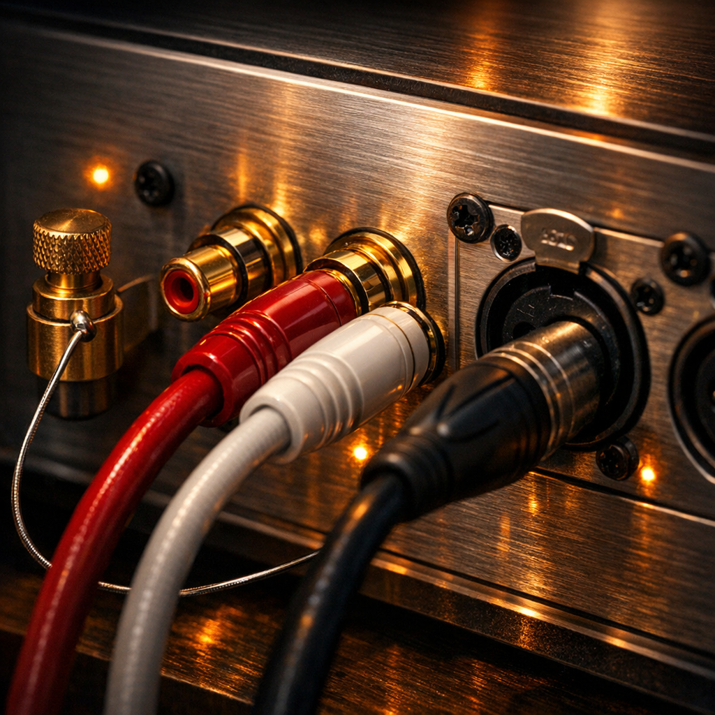
The most ubiquitous interface in consumer audio, RCA cables use a “center pin for signal, outer ring for ground” design. When connecting line-level sources like CD players, streamers, or external DACs, follow the standard color-coding: red for the right channel and white (or black) for the left. To ensure a professional-grade signal, use high-quality shielded cables to minimize electromagnetic interference (EMI). Ensure the “tulip” connectors are seated firmly; loose RCA connections are the leading cause of intermittent “popping” or signal dropouts.
XLR (Balanced) Connections
If your amplifier and source component feature XLR ports, these should be your preferred choice. XLR uses a three-pin configuration (ground, hot, and cold) to deliver a balanced signal. This architecture utilizes “common-mode rejection,” which effectively cancels out noise picked up along the cable run. This is essential for high-fidelity setups or cable runs exceeding 15 feet where external interference is a significant risk.
Phono Inputs and the Grounding Post
Turntables require a dedicated “Phono” input because their output signal is significantly weaker than “Line Level” sources. These inputs engage an internal RIAA equalization preamp to restore bass frequencies and boost the signal. Crucially, when using the Phono stage, you must connect the turntable’s thin spade-lug ground wire to the amplifier’s dedicated grounding post. Skipping this step is the primary cause of the intrusive 60Hz “ground hum” that can ruin your listening experience. If your amplifier lacks a Phono input, you must use an external phono preamp before connecting to a standard RCA “Aux” or “Line” input.
Digital Connectivity: Using Optical, Coaxial, and USB for High-Resolution Audio
While analog connections are the soul of high-fidelity audio, digital connectivity is the brain. Modern amplifiers often feature integrated Digital-to-Analog Converters (DACs), allowing you to bypass the inferior internal circuitry of your source devices for a cleaner signal path.
Optical (Toslink) and Coaxial S/PDIF
Optical connections utilize fiber-optic cables to transmit audio as pulses of light. This is your primary defense against ground loops and electromagnetic interference (EMI) because there is no physical electrical path between components. It is the gold standard for connecting televisions or game consoles to your amplifier. Coaxial connections, which require a dedicated 75-ohm digital cable, offer higher bandwidth and a tighter fit, often favored by audiophiles for shorter runs to minimize jitter. When wiring these, ensure your source device is set to “PCM” stereo output; many integrated stereo amplifiers cannot decode bitstream multi-channel formats (like Dolby Digital), which will result in no sound or digital “static.”
USB Audio: The High-Resolution Standard
For the highest fidelity from a PC, Mac, or dedicated network streamer, the USB (Type-B) input is essential. Unlike standard data transfers, high-end amplifiers utilize “asynchronous” USB technology. This allows the amplifier’s high-precision internal clock to control the data flow, rather than the computer’s noisy clock, virtually eliminating timing errors.
Expert Integration Tip
Digital signals are sensitive to physical degradation. When routing optical cables, avoid sharp bends that can fracture the internal fibers. For USB and Coaxial, keep cables as short as possible to prevent signal attenuation. Always cross-reference your source’s output sample rate (e.g., 192kHz) with your amplifier’s DAC specifications; if the source exceeds the amp’s ceiling, you will experience playback failure or audible distortion.
The Heavy Lifting: How to Properly Wire Passive Speakers to Your Amplifier
With your source components successfully integrated, the final—and most critical—physical step is routing power to your passive speakers. Unlike active monitors, passive speakers rely entirely on the amplifier’s internal circuitry for both signal and drive, making the quality of your connection paramount for sonic fidelity and hardware longevity.
First, select the appropriate speaker wire gauge (AWG). For standard home setups with cable runs under 50 feet, 16-gauge wire is sufficient; however, for longer runs or low-impedance (4-ohm) speakers, 14-gauge or 12-gauge is preferred to minimize resistance and signal loss. When preparing the wire, strip approximately half an inch of insulation, ensuring the copper strands are tightly twisted and not frayed.
The “Golden Rule” of speaker wiring is maintaining absolute polarity. Every speaker and amplifier terminal is color-coded: Red (Positive/+) and Black (Negative/-). You must connect the red terminal on your amplifier to the red terminal on the corresponding speaker. Crossing these wires results in “out-of-phase” audio, characterized by a thin, hollow soundstage and a significant cancellation of bass frequencies.
For the most reliable connection, utilize banana plugs or spade connectors rather than bare wire. These terminations prevent copper oxidation and eliminate the risk of “stray strands”—a single rogue wire touching the amplifier’s chassis or an adjacent terminal can cause a short circuit, potentially frying the output transistors. Once seated, hand-tighten the binding posts firmly. Before powering on, perform a final visual sweep: ensure no metal-on-metal contact exists between terminals and that each channel (Left and Right) is correctly mapped. Mastering this physical link ensures the amplifier’s power is delivered with the precision required for high-resolution performance.
Integrating a Subwoofer: LFE vs. Speaker-Level Connection Methods
To achieve a truly cinematic or high-fidelity soundstage, integrating a subwoofer is essential for handling the non-directional low frequencies your main speakers might struggle to reproduce. There are two primary ways to facilitate this connection, depending on your amplifier’s features and your specific audio goals.
The LFE (Low-Frequency Effects) Connection
Most modern AV receivers and many integrated amplifiers feature a dedicated “Sub Out” or “LFE” port. This is a line-level connection typically made using a single shielded RCA cable. Using the LFE output is the most efficient method because it allows the amplifier’s internal processor to manage the crossover—the point where the main speakers stop playing bass and the subwoofer takes over. When using this method, turn the “Crossover” or “Low Pass” dial on the back of your subwoofer to its maximum setting (or “bypass” mode) to prevent “cascading filters,” which can cause muddy, distorted bass.
The Speaker-Level (High-Level) Connection
If you are using a vintage or high-end stereo amplifier that lacks a dedicated subwoofer output, you must use a speaker-level connection. This involves running an additional set of speaker wires from the amplifier’s main binding posts directly to the subwoofer’s “High-Level Inputs.” Because the subwoofer has a high input impedance, it draws negligible power, meaning it won’t strain your amplifier or change the load seen by the main speakers. Many audiophiles prefer this method for music because it ensures the subwoofer receives the exact same sonic signature and timing as the main speakers.
Regardless of the method, ensure you maintain correct polarity (positive to positive, negative to negative). Once connected, use the subwoofer’s phase switch—usually 0° or 180°—to ensure the sub’s driver is moving in sync with your main speakers, preventing frequency cancellation at the crossover point.
Advanced Configurations: Bi-Wiring, Bi-Amping, and Multi-Zone Setups
For enthusiasts seeking to push their system’s boundaries, standard single-wire setups may not suffice. Bi-wiring involves running two separate sets of speaker cables from a single amplifier output to a speaker equipped with dual binding posts. By separating the high-frequency and low-frequency signal paths, you minimize the electromagnetic interference caused by the large drivers’ back-EMF, often resulting in a more detailed high-end. Crucially, before connecting, you must remove the brass jumper straps on the speaker terminals; failing to do so renders the bi-wiring redundant.
Bi-amping takes this a step further by utilizing two dedicated amplifier channels per speaker—one for the tweeter and one for the woofer. This provides significantly more headroom and prevents power-hungry bass frequencies from modulating the high-frequency signal. If you are using two different amplifiers (vertical bi-amping), ensure they have identical gain stages to maintain a cohesive soundstage.
Finally, Multi-Zone setups allow your amplifier to serve as the hub for audio in different rooms. Many integrated amplifiers feature “Speaker A/B” switches or dedicated “Zone 2” line-outs. When utilizing a “Speaker B” output to drive a second pair of speakers simultaneously, you must calculate the combined impedance load. Wiring two pairs of 8-ohm speakers in parallel creates a 4-ohm load. If your amplifier is only rated for 8 ohms, running both zones simultaneously can lead to overheating or permanent hardware failure. For multi-room stability, always verify that your amplifier’s power supply can handle the decreased resistance of a multi-speaker load.
Network and Smart Integration: Connecting via Ethernet and HDMI ARC
Modern integrated amplifiers often function as the central hub of a smart home entertainment system, necessitating high-bandwidth data connections. Integrating your amplifier via HDMI ARC/eARC and Ethernet ensures a seamless, high-resolution experience that traditional analog cables cannot match.
HDMI ARC and eARC Integration
HDMI ARC (Audio Return Channel) and its successor, eARC (Enhanced Audio Return Channel), allow your TV to send audio back to the amplifier through the same cable that sends video to the screen. This eliminates the need for a separate optical cable and enables CEC (Consumer Electronics Control), which allows your TV remote to control the amplifier’s volume and power. To connect, use a High-Speed HDMI cable (v2.0 for ARC; v2.1 for eARC) and locate the HDMI port on your TV explicitly labeled “ARC” or “eARC.” Connect this to the “HDMI Out” or “ARC” port on your amplifier. If no sound is produced, navigate to your TV’s audio menu and ensure the digital output is set to “PCM” (for stereo amps) or “Bitstream” (for multi-channel receivers).
Ethernet for Stable High-Resolution Streaming
While many modern amplifiers offer Wi-Fi, a hardwired Ethernet connection is the expert’s choice for critical listening. High-resolution audio files—such as 24-bit/192kHz FLAC or DSD—require a consistent data flow that Wi-Fi can struggle to maintain due to signal interference. Connect a Cat6 or Cat7 cable from your network switch or router directly to the RJ45 LAN port on the back of the amplifier. This wired link provides the lowest possible jitter and latency when streaming from local NAS (Network Attached Storage) drives or high-fidelity services like Tidal and Qobuz. Once connected, the amplifier will be discoverable by DLNA, Roon, or Spotify Connect, ensuring your smart setup remains both convenient and audiophile-grade.
Shielding Your Sound: Preventing Ground Loops and Electromagnetic Interference
Even the most meticulously wired system can fall victim to the dreaded 60Hz hum or a persistent high-pitched digital whine. This unwanted noise generally stems from two culprits: ground loops and Electromagnetic Interference (EMI). To achieve professional-grade audio, you must proactively manage these environmental factors during the installation phase.
Ground loops occur when multiple components are grounded at different electrical potentials, creating a circulating current that manifests as a low-frequency hum. The most effective preventative measure is “star grounding”—plugging all your audio components into a single high-quality power conditioner or a shared terminal. This ensures every piece of gear “sees” the same ground level. If a hum persists despite unified power, a ground loop isolator on your RCA lines can break the loop while maintaining signal integrity.
EMI and Cable Management are equally critical. Your signal cables (RCA, phono, and speaker wires) act like antennas for interference emitted by power bricks, Wi-Fi routers, and LED dimmers. To minimize this, never run power cords parallel to signal cables. If they must cross, ensure they do so at a 90-degree angle to minimize the induction of noise. Furthermore, invest in double-shielded interconnects. While budget cables might suffice for short distances, longer runs require robust copper braiding or foil shielding to block Radio Frequency Interference (RFI).
Expert Tip: If you experience a “buzz” that fluctuates with computer activity, you are likely dealing with USB bus noise. Utilizing a USB galvanic isolator or switching to an optical (Toslink) connection—which is non-conductive—can instantly eliminate this digital interference by physically breaking the electrical path between the noisy source and your amplifier.
Final Calibration: Testing Signal Flow and Optimizing Gain Stages
With the physical wiring complete, you transition from the mechanical setup to the sonic calibration. The goal of this final stage is to optimize gain staging—the process of managing the relative volume levels of each component in your signal chain to ensure the highest possible signal-to-noise ratio without inducing clipping or audible distortion.
Begin by setting all volume controls on your source devices and amplifier to zero. Power on your source first, followed by your preamp (if applicable), and finally your power amplifier; this specific sequence protects your speakers from “turn-on” voltage spikes that can damage delicate voice coils. Play a high-quality, familiar track and slowly increase the source volume to approximately 75–80% of its range. This provides a clean, robust signal for the amplifier to process. Then, gradually raise the amplifier’s gain or volume knob to your preferred listening level. If you hear a persistent hiss when no music is playing, your gain structure is likely too high at the amplifier stage; conversely, if the audio sounds thin or “crunchy” at low volumes, your source signal is likely underpowered.
Next, perform a phase check. If the center image of the vocals feels “hollow” or the bass is unexpectedly weak despite correct wiring, re-verify the speaker polarity. A single inverted wire will cause phase cancellation, stripping the “impact” from your audio. Finally, monitor for clipping during peak transients. If your amplifier’s “Clip” or “Peak” indicator flickers, reduce the input signal immediately to prevent heat buildup and potential hardware failure. Mastering this delicate balance between input sensitivity and output power is the final step in ensuring your system delivers crystal-clear, high-fidelity performance.
Troubleshooting Common Connection Issues: From Hum to No Sound
Even after a meticulous physical setup, you may encounter the frustration of silence, distortion, or unwanted noise. Effective troubleshooting requires a systematic isolation process to identify whether the failure is at the source, the amplifier, or the transducers.
If you are met with total silence, start by checking the amplifier’s “Protect Mode” indicator. Modern amplifiers enter a self-preservation state if they detect a short circuit—often caused by a single stray strand of speaker wire bridging the positive and negative terminals. If the amp is on but silent, verify the “Tape Monitor” or “Mute” settings, and ensure the A/B speaker selector matches the physical terminals you used. For bi-wire capable speakers, ensure the gold-plated bridge jumpers are securely fastened if you are using a standard single-run connection; otherwise, the tweeter or woofer will remain disconnected.
Audible hum or buzz—specifically a steady 60Hz drone—is usually the result of a ground loop. If the shielding techniques discussed previously haven’t resolved this, try the “process of elimination” method: disconnect all input cables and see if the hum persists. If it vanishes, reconnect components one by one until the noise returns to identify the culprit. Conversely, a high-pitched hiss often points to a “gain staging” error, where the source volume is too low and the amplifier’s gain is cranked too high, raising the noise floor into the audible range.
Finally, if the audio sounds “thin” or lacks a centered image, you likely have a phase reversal. Double-check that the polarity (+/-) is consistent across all channels. If one speaker is wired in reverse, their sound waves will physically cancel each other out, destroying your low-end response and soundstage. Always power down the system before swapping wires to prevent thermal runaway or fuse failure.
Have questions or your own tips to share? Drop a comment below!