In the world of high-performance power electronics, the humble capacitor clamp is frequently dismissed as a mere mechanical afterthought. However, viewing it as just a mounting bracket is a critical engineering oversight. Far from being a passive component, the right clamp functions as a vital thermal interface, dictating how effectively heat is drawn away from the core to prevent premature electrolyte degradation.
Beyond thermal management, your choice of clamp is the primary defense against vibration-induced mechanical stress, which can lead to catastrophic terminal fatigue in high-demand environments. This guide moves beyond basic assembly to explore the sophisticated physics of capacitor mounting. We will examine how material thermal conductivity, mounting geometry, and precision clamping pressure directly impact MTBF (Mean Time Between Failures), ensuring your system’s longevity isn’t compromised by a component that was “just meant to hold on.”
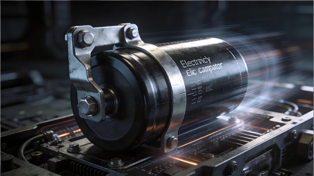
The Mechanical-Thermal Interface: Why a Clamp Is More Than Just a Fastener
In high-power electrical engineering, viewing a capacitor clamp as a simple mechanical stay is a critical oversight. The clamp functions as the primary thermal bridge between the component’s aluminum housing and the chassis or heat sink. Because electrolytic capacitors generate internal heat through ripple current and equivalent series resistance (ESR), managing this thermal load is paramount to maintaining dielectric integrity. An engineered clamp optimizes the contact surface area, minimizing the thermal resistance ($R_{th}$) between the capacitor and the ambient environment. When a clamp lacks precision—either through poor material conductivity or suboptimal geometry—it introduces air gaps that act as thermal insulators, leading to localized “hot spots” that accelerate electrolyte evaporation and drastically reduce Mean Time Between Failures (MTBF).
Furthermore, the clamp serves as a vital damping mechanism for mechanical-thermal synergy. In high-vibration environments, such as industrial motor drives or EV powertrains, mechanical resonance can lead to micro-fractures in the internal lead-out tabs. A high-quality clamp provides uniform circumferential pressure, which stabilizes the internal winding stack against these stresses. However, this is a delicate balance; excessive torque or an improperly sized clamp can deform the thin-walled canister, compromising the safety vent or the hermetic seal. This deformation not only risks leakage but also alters the internal pressure dynamics, further compounding thermal issues. By selecting a clamp designed for high thermal dissipation and mechanical dampening, engineers ensure the capacitor operates within its specific temperature derating curve, preventing the catastrophic “thermal runaway” cycle where rising temperatures lead to higher ESR, which in turn generates even more heat.
Material Science Matters: Comparing Metal vs. Plastic Clamps for Heat Management
In high-power electronics, the material composition of a capacitor clamp is a critical variable in the total thermal resistance equation ($R_{\theta}$). Metal clamps, typically fabricated from aluminum or zinc-plated steel, offer high thermal conductivity that polymers simply cannot match. Aluminum, possessing a thermal conductivity of approximately 205 W/m·K, effectively transforms the clamp into a secondary heatsink. By increasing the effective surface area and creating a low-resistance conductive path to the chassis, metal clamps facilitate the rapid dissipation of latent heat generated by Equivalent Series Resistance (ESR). This is vital for maintaining the internal core temperature of electrolytic capacitors; according to the Arrhenius Law, a mere 10°C rise in operating temperature can halve the component’s service life due to accelerated electrolyte evaporation.
Conversely, plastic or glass-reinforced nylon clamps are often favored for their inherent dielectric isolation and superior vibration-damping characteristics. In environments subject to high-frequency mechanical stress, polymers can absorb energy that might otherwise cause terminal fatigue. However, from a thermal perspective, they act as insulators (often $< 1$ W/m·K). A poorly specified plastic clamp can create a "thermal blanket" effect, trapping heat at the capacitor's midpoint and creating localized hot spots.
Engineers must also account for the Coefficient of Thermal Expansion (CTE). Metal clamps provide a rigid, stable mounting force across wide temperature swings, whereas some polymers may experience “creep” or loss of tension over time when subjected to thermal cycling. This loss of torque reduces the pressure at the thermal interface, significantly increasing contact resistance. For high-ripple applications where thermal runaway is a risk, a metal clamp paired with a high-performance thermal interface material (TIM) represents the gold standard for maximizing component longevity.
Impact on Electrolyte Longevity: Managing the Internal Thermal Gradient
The relationship between a capacitor’s service life and its operating temperature is governed by the Arrhenius equation, which dictates that for every 10°C increase in core temperature, the component’s life expectancy is halved. While airflow and heat sinks are primary cooling strategies, the capacitor clamp serves as the critical mechanical-thermal bridge that manages the internal thermal gradient. In high-ripple current applications, internal heat builds up within the electrolyte and foil windings. Without an optimized clamping solution, this heat remains trapped, causing the electrolyte to vaporize and permeate through the end seal—a process known as “dry-out.”
A precision-engineered metal clamp acts as an auxiliary heat sink, reducing the thermal resistance ($\theta_{ca}$) between the capacitor case and the chassis. By maximizing the surface area contact and ensuring high contact pressure, the clamp facilitates a more uniform heat distribution across the cylindrical surface. This prevents localized “hot spots” within the capacitor core that accelerate ESR (Equivalent Series Resistance) rise. As ESR increases, the device generates even more internal heat under load, creating a destructive thermal runaway loop that leads to premature failure or catastrophic outgassing.
Furthermore, the clamp’s role in vibration mitigation is inextricably linked to thermal stability. In high-stress environments, mechanical resonance can cause micro-fretting at the internal lead-to-tab connections. These micro-fractures increase resistive heating at the point of contact, raising the internal temperature independently of the ambient environment. A high-quality clamp provides the damping necessary to suppress these vibrations, ensuring that the internal mechanical integrity—and by extension, the chemical stability of the electrolyte—remains uncompromised over the system’s intended lifecycle. Proper clamp selection is, therefore, not a mounting afterthought but a fundamental requirement for thermal management and MTBF (Mean Time Between Failures) optimization.
Vibration Damping and Structural Integrity in High-Stress Electrical Environments
In high-stress electrical environments—ranging from industrial motor drives to aerospace power conversion—vibration is a silent killer of large-format capacitors. While often viewed as a simple mounting bracket, the capacitor clamp serves as the primary defense against mechanical resonance and fatigue. When a capacitor is subjected to sustained harmonic vibration or high-G shocks, the internal foil windings and lead tabs experience significant cantilevered stress. Without a precision-engineered clamp, these micro-oscillations can cause work-hardening of internal connections, leading to microscopic fractures and a subsequent rise in Equivalent Series Resistance (ESR).
Furthermore, the structural integrity of the clamp-to-chassis interface directly dictates the component’s thermal stability. Inadequate damping allows for “fretting,” where the capacitor housing moves against the mounting surface, creating frictional heat and compromising the thermal path established by the thermal interface material (TIM). High-performance clamps often incorporate specialized elastomeric liners or specific geometric ribbing to decouple the capacitor from chassis-borne vibrations. This damping effect is crucial for preserving the hermetic seal of the capacitor; excessive mechanical stress can cause seal deformation, leading to electrolyte leakage and catastrophic dry-out.
Engineers must evaluate the damping coefficient of the clamp material alongside its clamping force. A clamp that is too rigid may transmit high-frequency transients directly into the component’s internal architecture, while one that is too compliant may allow for low-frequency oscillations that strain the terminal busbars. Achieving the correct balance ensures that the capacitor remains a static element in a dynamic environment, protecting the delicate internal chemistry from the physical rigors of the application and preventing premature failure due to mechanical-thermal synergy.
Optimizing Airflow and Surface Contact: The Role of Clamp Geometry in System Cooling
In high-density power electronics, the physical architecture of a capacitor clamp acts as a critical variable in the thermal management equation, moving beyond simple retention to influence both conductive and convective heat transfer pathways. The geometry of the clamp dictates the “thermal footprint” of the component; a clamp with a wider surface area increases the contact patch for primary conduction but can simultaneously act as a thermal bottleneck if it creates stagnant air pockets or “shrouds” the capacitor’s casing.
To optimize cooling, engineers must balance surface contact pressure with aerodynamic profiles. High-performance clamps often feature “vented” or “cut-away” geometries that facilitate the “chimney effect” in vertical mountings. By minimizing the clamp’s cross-sectional profile in the direction of airflow, designers can prevent boundary layer disruption and ensure that forced or natural convection reaches the lower sections of the capacitor—the area most susceptible to heat accumulation near the PCB.
Furthermore, the geometry affects the interface’s thermal resistance ($R_{th}$). A clamp designed with a slight radial tension (ribbed or fluted designs) ensures uniform pressure around the circumference of the capacitor. This uniformity is vital when utilizing Thermal Interface Materials (TIMs), as uneven geometry can lead to “pump-out” or dry spots, significantly increasing the internal thermal gradient. Conversely, overly bulky clamps can increase the thermal mass of the assembly, leading to heat retention during peak loads. By selecting a clamp with a low-profile, high-strength geometry, you enable maximum bypass airflow while maintaining the mechanical rigidity necessary to withstand thermal expansion and contraction cycles without compromising the thermal bridge to the heat sink or chassis.
Preventing Mechanical Deformation: Balancing Mounting Torque with Component Protection
Achieving the optimal mounting torque is a precision balancing act that defines the boundary between structural stability and catastrophic failure. While a clamp must be tight enough to ensure a low-impedance thermal path, excessive radial pressure can lead to mechanical deformation of the capacitor’s cylindrical housing. This deformation is not merely aesthetic; it exerts inward stress on the internal “jelly roll”—the tightly wound layers of dielectric and foil—potentially altering the uniform distance between plates. Even a microscopic compression of these layers can lead to localized increases in the electric field, premature dielectric breakdown, or a rise in Equivalent Series Resistance (ESR) due to compromised internal contact.
The engineering challenge lies in the fact that thermal dissipation relies heavily on surface contact. To maximize the transfer of heat from the canister to the clamp and subsequently to the chassis, the interface must be void of air gaps. However, as torque increases, the risk of “pinching” the component grows, particularly in aluminum electrolytic capacitors where the casing is relatively thin. Expert-level installation requires adhering to specific Newton-meter (N·m) ratings that account for the material’s thermal expansion coefficient.
Furthermore, engineers must consider the “creep” behavior of the clamp material. Plastic clamps may relax over time under high thermal loads, leading to a loss of tension and increased vibration sensitivity, while metal clamps provide more consistent pressure but require precision gaskets or sleeves to prevent “biting” into the capacitor’s insulating wrap. By quantifying the clamping force, designers can ensure that the component remains seated during high-vibration events without inducing the mechanical strain that accelerates electrolyte degradation or physical rupturing of the safety vent. Proper torque isn’t just about security; it is a critical variable in maintaining the capacitor’s internal geometry and, by extension, its operational lifespan.
Environmental Resistance: Selecting Clamps for Corrosive or High-Humidity Settings
In high-humidity or chemically aggressive environments, a capacitor clamp’s role transitions from a mechanical support to a critical barrier against systemic failure. The primary engineering challenge in these settings is preventing the degradation of the mechanical-thermal interface. When a clamp succumbs to oxidation or galvanic corrosion, the resulting oxide layer acts as a thermal insulator, significantly increasing the thermal impedance between the capacitor’s aluminum casing and the heat-dissipating chassis. This leads to localized “hot spots” that accelerate electrolyte evaporation, even if the ambient temperature remains within nominal limits.
Material selection must be governed by the galvanic series to prevent accelerated corrosion at the point of contact. While standard zinc-plated steel may suffice for controlled environments, high-salinity or industrial atmospheres necessitate 304 or 316 stainless steel, often treated with passivation to enhance the protective chromium oxide layer. However, engineers must account for the slightly lower thermal conductivity of stainless steel compared to carbon steel by optimizing surface contact area.
Furthermore, in high-humidity settings, the geometry of the clamp must facilitate drainage to prevent moisture entrapment. Crevice corrosion can occur in the microscopic gaps between the clamp and the capacitor wall, leading to pitting that can eventually breach the component’s hermetic seal. To mitigate this, specialized coatings—such as thermally conductive epoxies or nylon-11—are often employed. These coatings provide high dielectric strength and chemical resistance while maintaining a low thermal resistance path. By selecting a clamp that maintains its structural and chemical integrity against environmental stressors, you ensure that the thermal dissipation path remains consistent over the component’s entire lifecycle, preventing the premature dielectric breakdown associated with moisture-induced surface tracking.
Common Mounting Failures and Their Impact on Circuit MTBF (Mean Time Between Failures)
In the reliability engineering landscape, the Mean Time Between Failures (MTBF) of a power electronic assembly is disproportionately sensitive to the thermal and mechanical stability of its largest passive components. While a capacitor may be rated for 10,000 hours at 105°C, this figure is a theoretical maximum that assumes ideal heat rejection. Common mounting failures—such as insufficient clamping torque or the use of clamps with poor thermal conductivity—introduce parasitic thermal resistance ($R_{th}$) at the case-to-clamp interface. This results in an elevated core temperature; according to the Arrhenius Law, every 10°C rise in operating temperature effectively halves the component’s lifespan due to accelerated electrolyte evaporation and electrochemical degradation.
Beyond thermal concerns, mechanical mounting failures significantly degrade MTBF through vibrational fatigue. A clamp that does not provide uniform circumferential pressure or fails to account for the component’s center of gravity can allow micro-movements during high-frequency operation or transit. These oscillations induce stress on the internal foil-to-terminal tabs and external solder joints, leading to increased Equivalent Series Resistance (ESR) or open-circuit failures.
Furthermore, “over-clamping” represents a critical failure mode where excessive compressive force deforms the aluminum can, potentially compromising the internal winding geometry and creating localized hotspots. This mechanical deformation disrupts the uniform thermal gradient required for stable operation. Consequently, MTBF is not merely an intrinsic property of the capacitor itself but a dynamic variable dictated by the clamp’s ability to maintain structural integrity and thermal equilibrium. Selecting a precision-engineered mounting solution is therefore a prerequisite for meeting the rigorous reliability targets of industrial and automotive power systems.
Engineering Best Practices for Integrating Capacitor Clamps into High-Power Assemblies
Integrating capacitor clamps into high-power assemblies demands a holistic approach where mechanical constraints are balanced against thermal and electromagnetic requirements. To optimize the Mean Time Between Failures (MTBF), engineers must treat the clamp-to-can interface as a critical thermal junction. A primary best practice is the application of high-conductivity Thermal Interface Materials (TIMs) or phase-change foils between the capacitor wall and the clamp’s inner diameter. This minimizes the contact resistance ($R_{\theta, \text{interface}}$), ensuring that the clamp acts as an effective heat sink rather than a thermal insulator.
Furthermore, strategic spatial orientation is paramount. In forced-air cooling systems, clamps should be positioned to minimize “dead zones” where stagnant air might accumulate near the capacitor’s base or pressure relief vent. For systems utilizing cold plates, ensuring the clamp geometry facilitates a direct, low-impedance thermal path to the cooling surface is essential for managing high ripple current loads.
Mechanical stability must also account for the Coefficient of Thermal Expansion (CTE) mismatch between the aluminum capacitor housing and the clamp material. Under high-load cycling, differential expansion can lead to mechanical fatigue or stress on the capacitor’s header seal. Utilizing “constant-tension” clamp designs or compliant elastomeric liners can accommodate this “thermal breathing” without compromising structural integrity or losing mounting torque.
Finally, in high-frequency applications, the electrical potential of metal clamps must be addressed. Clamps should be effectively grounded to the system chassis to prevent them from acting as floating antennas or parasitic capacitive couplers, which can introduce EMI/RFI noise into sensitive control circuitry. By adhering to these rigorous integration standards, engineers transform the capacitor clamp from a mere mounting accessory into a functional component that actively extends system longevity.
Have questions or your own tips to share? Drop a comment below!